
The Raspberry Pi is a Linux computer. But unlike most desktop and laptop Linux computers, users have access to a row of pins that can be used as inputs or outputs. These 40 pins are called GPIO (General Purpose Input Output) pins. This Raspberry Pi GPIO tutorial aims to help you program these pins for your purpose.
Raspberry Pi GPIO Pinout
The GPIO pins for the newer Raspberry Pi models (starting with B+) are laid out as follows:
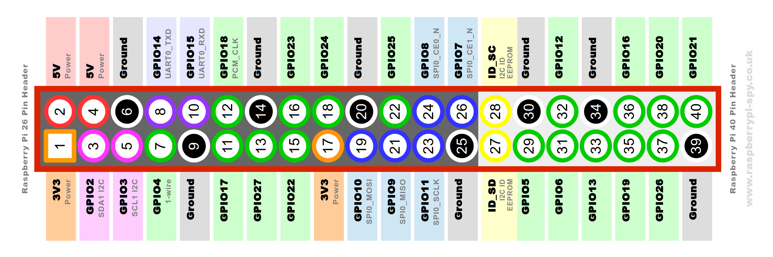
Here we see two ways to identify a pin: by board name or by its Broadcom chip name (a.k.a. BCM). The numerically arranged names are the board names while the GPIO# are the BCM names. Unfortunately, the BCM names can never be arranged like the board names because of how the Raspberry Pi PCB is designed. From here on, I will refer to the board names by numbers only and the BCM pins by GPIO numbers.
The pins can be grouped into four main groups: Power, Ground, GPIO, and EEPROM. The Raspberry Pi can provide 3.3V and 5V voltage sources on pins 1, 2, and 4. The ground pins are spread out to pins 6, 9, 14, 20, 25, 34 and 39.
The GPIO pins can be grouped into normal, UART, SPI, and I2C. They are colored green, purple, blue and pink as per the diagram above. Note that all GPIO pins operate at 3.3V so stay away from devices that go beyond this voltage.
We will look closer at UART, SPI, and I2C in separate tutorials. You might want to read my primers on UART, SPI, and I2C as an introduction to these communication methods.
Finally, the EEPROM pins are used by HATS (hardware attached on top) for identification. Each HAT has its own EEPROM ID which is detected by the Raspberry Pi when attached. The RPi, in turn, uses the ID to automatically load the required driver.
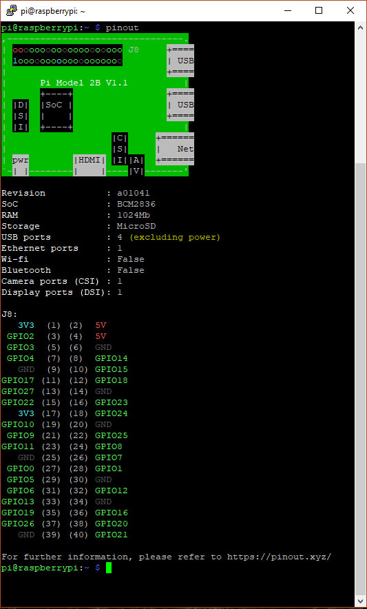
You can view the GPIO pin names on the Raspberry Pi terminal using the command pinout. Here’s what it looks like:
Programming the GPIO Pins
Now that we are introduced to the Raspberry Pi GPIO pins, it’s time to make them useful!
There are several ways to program the Raspberry Pi GPIO pins but I found Python to be the easiest way. Specifically, we’ll be using the RPi.GPIO Python module which already comes with the latest Raspbian distribution.
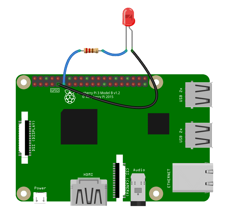
We’ll connect a LED to GPIO17 of the Raspberry Pi like this:
Next, we will open the Python terminal:
pi@raspberrypi:~ $ python
Python 2.7.13 (default, Nov 24 2017, 17:33:09)
[GCC 6.3.0 20170516] on linux2
Type "help", "copyright", "credits" or "license" for more information.
>>>
In order to use the GPIO module I mentioned, we need to import it like this:
>>> import RPi.GPIO as GPIO
Next, we need to specify if we will be referring to the pins by their board name or by their BCM name. This is done through:
>>> GPIO.setmode(GPIO.BCM)
Then we setup the pin as either output or input. Since we connected a LED to GPIO17, this would be the right call
>>> GPIO.setup(17, GPIO.OUT)
Now to make GPIO17 high which will light up the LED, we use this command:
>>> GPIO.output(17, GPIO.HIGH)
This is how we turn off the LED:
>>> GPIO.output(17, GPIO.LOW)
Once we’re done, we need to tell the Raspberry Pi that clear up the pin we just used:
>>>GPIO.cleanup()
If we don’t use the .cleanup() function, a warning is issued if ever we used the same GPIO pin again even if we have already exited the Python terminal:
__main__:1: RuntimeWarning: This channel is already in use, continuing anyway. Use GPIO.setwarnings(False) to disable warnings.
You can disregard using GPIO.cleanup() and just use GPIO.setwarnings(False) to get rid of the warning message above. But using cleanup() is a good practice because it resets the pin to its default state. This would prevent damaging situations like a previously high pin connected to ground.
Python Script for Blinking a LED
Of course, you would want a single page program and not just commands typed into the terminal. You can write the commands above (with some add-ons) on a file:
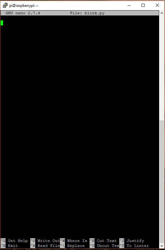
pi@raspberrypi:~ $ sudo nano blink.py
This will bring up the Nano file editor.
Then we type this Python script:
import RPi.GPIO as GPIO
import time as time

GPIO.setmode(GPIO.BCM)
GPIO.setup(17, GPIO.OUT)

while True:
     GPIO.output(17, GPIO.HIGH)
     time.sleep(1)
     GPIO.output(17, GPIO.LOW)
     time.sleep(1)

GPIO.cleanup()
Press CTRL+X, press Y to save, then press enter to use the same file name.
To run the script, invoke Python:
pi@raspberrypi:~ $ python blink.py
The LED should now be blinking!
Now we added some things on the script not used in the Python terminal. I’ll start with this:
import time as time
This imports the time module which will be used to insert a delay between turning on and turning off the LED. The delay command for Raspberry Pi in Python is:
time.sleep(1)
Where the number 1 is the delay in seconds.
Also, we need to create a loop to keep the LED blinking using
while True:
To stop the blinking, just use CTRL+C (Keyboard Interrupt)
Using GPIO Pin as Input
I think you now have an idea to make a Raspberry Pi GPIO pin as input. To make a pin as input, we will now use this:
GPIO.setup(22, GPIO.IN)
To read an input pin, we use the GPIO.input(22) function which returns 1 if the input is high and 0 otherwise.
We will now attach a button to GPIO22 for this next example:
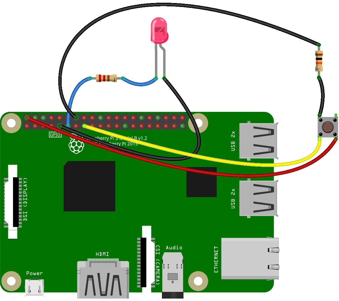
This script turns on the LED when the button is pressed:
import RPi.GPIO as GPIO

GPIO.setmode(GPIO.BCM)
GPIO.setup(17, GPIO.OUT)
GPIO.setup(22, GPIO.IN)

while True:
     if GPIO.input(22):
        GPIO.output(17, GPIO.HIGH)
     else:
        GPIO.output(17, GPIO.LOW)

GPIO.cleanup()
Similar to the previous script, we can exit this program using CTRL+C.
In the next part of my article, I will show how to control a servo motor using the Raspberry Pi. Thanks for reading!

