
For the next part of the series on Raspberry Pi, I will show how to produce a PWM signal from a pin. Moreover, I will show you how to control single and multiple servo motors in this Raspberry Pi PWM tutorial.
Raspberry Pi PWM Pin
Strictly speaking, there is only one user-accessible PWM pin on all Raspberry Pi models and it’s GPIO18.

This pin can be used using the same RPi.GPIO Python module I used in the previous tutorial.
Similar to using any GPIO pin, we must first import the GPIO module:
import RPi.GPIO as GPIO
Then, the pin name convention to be used must be set up:
GPIO.setmode(GPIO.BCM)
Next, the pin should be declared as output:
GPIO.setup(18, GPIO.OUT)
After that, we create a PWM object like this:
pwm = GPIO.PWM(18,1000)
Where 1000 is the PWM frequency in Hertz. The PWM signal appear on the pin only after this line is called:
pwm.start(50)
Where 50 is the duty cycle of the PWM signal.
You can stop the PWM signal using:
pwm.stop()
Also, you can change the frequency once it’s running using:
pwm.ChangeFrequency(freq)
Furthermore, you can change the duty cycle using:
pwm.ChangeDutyCycle(dc)
Fading a LED
We can use PWM to fade a LED connected to GPIO18 using this diagram:

This will be the Python script for fading the LED:
import RPi.GPIO as GPIO
import time as time

GPIO.setmode(GPIO.BCM)
GPIO.setup(18, GPIO.OUT)

pwm = GPIO.PWM(18, 50) # GPIO18, frequency=50Hz
pwm.start(0)
try:
   while True:
     for dc in range(0, 101, 5):
        pwm.ChangeDutyCycle(dc)
        time.sleep(0.1)
     for dc in range(100, -1, -5):
        pwm.ChangeDutyCycle(dc)
        time.sleep(0.1)
except KeyboardInterrupt:
   pass
pwm.stop()
GPIO.cleanup()
There are some new things in this script not found in my previous tutorial. Of course, import RPi.GPIO is required while import time is used for introducing a time delay.
I used a try-except syntax for a more orderly program exit. When the program detects CTRL+C or KeyboardInterrupt, it exits the while loop and then stops the PWM. Finally, it proceeds to clean up the used GPIO pin.
Inside the while loop are two for loops:
for dc in range(0, 101, 5):
   pwm.ChangeDutyCycle(dc)
   time.sleep(0.1)
for dc in range(100, -1, -5):
   pwm.ChangeDutyCycle(dc)
   time.sleep(0.1)
The first for loop increments the duty cycle by 5 starting from 0 to 100 (101 is not included in the loop). This continually increases the intensity of the LED. The second for loop decrements the duty cycle by 5 from 100 to 0. Similarly, this decreases the intensity of the LED.
Use PWM to Control a Servo Motor
A servo motor is controllable through PWM. Specifically, its arm position depends on the width of the pulse applied to it. This diagram summarizes how a servo motor is controlled through PWM.
Centering the servo arm requires a 1.5 ms pulse width. Furthermore, if we are to produce this using Raspberry Pi PWM, we must consider both the duty cycle and frequency of the signal.
A 1.5 ms PWM signal can be produced with a frequency of 500 Hz and a 75% duty cycle:
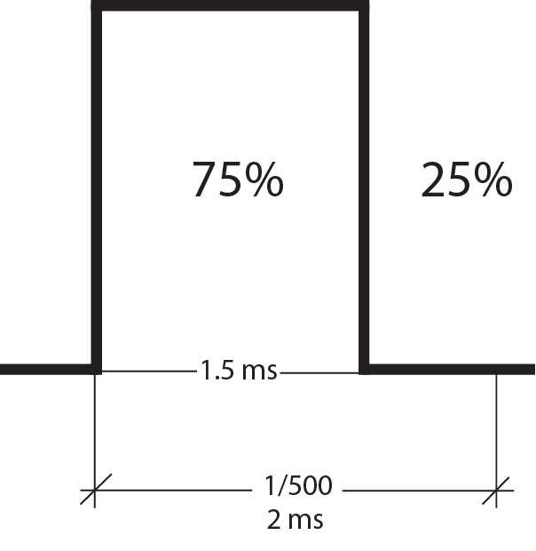
Increasing the duty cycle increases the pulse width, ending with 2 ms at 100% duty cycle. Similarly, the duty cycle can be decreased up to 50% for a 1 ms pulse width. That covers the range of the pulses for controlling the servo motor!
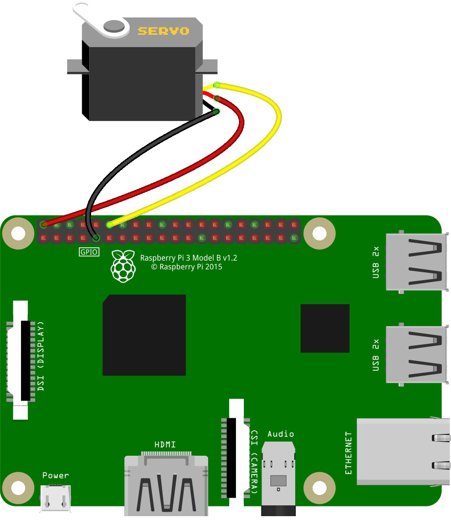
I will be using this diagram for the next example script:
import RPi.GPIO as GPIO
import time as time

GPIO.setmode(GPIO.BCM)
GPIO.setup(18, GPIO.OUT)

servo = GPIO.PWM(18,500)
servo.start(0)
try:
   while True:
     for dc in range(50,101,5):
        servo.ChangeDutyCycle(dc)
        time.sleep(0.5)
     for dc in range(100,45,-5):
        servo.ChangeDutyCycle(dc)
        time.sleep(0.5)
except KeyboardInterrupt:
   pass
servo.stop()
GPIO.cleanup();
Here, I used servo as the name of the PWM object attached to GPIO18 with frequency of 500 Hz.
servo = GPIO.PWM(18,500)
Then to sweep the arm back and forth, I used to same for loop as the fading LED example, only that I changed the range of duty cycle from 50 to 100 and then back to 50:
for dc in range(50,101,5):
   servo.ChangeDutyCycle(dc)
   time.sleep(0.5)
for dc in range(100,45,-5):
   servo.ChangeDutyCycle(dc)
   time.sleep(0.5)
The rest is just like the fading LED script. That’s it!
Multiple Raspberry Pi PWM Pins
The problem with using the RPi.GPIO library is that it’s restricted to GPIO18 only. What if I want to use multiple PWM signals?
Thankfully, an external Python library named pigpio exists. This library allows us to use any GPIO pin for PWM.
To install pigpio, use these commands:
wget abyz.co.uk/rpi/pigpio/pigpio.zip
unzip pigpio.zip
cd PIGPIO
make
sudo make install
Pigpio uses a daemon called pigpiod. This daemon must be running in the background for us to use the servo functions of the library. Thus, we must run the daemon once the whole pigpio library is installed using:
pi@raspberrypi:~ $ pigpiod
After that, we can now freely use all the pigpio functions in the python terminal or in a python script.
Now to use the pigpio library, we need to import it:
import pigpio
And then declare an object using whatever name you like. For example:
pi = pigpio.pi()
Generating a pulse only requires this function:
pi.set_servo_pulsewidth(18, 800)
Where 18 is the GPIO pin number and 800 is the pulsewidth in microseconds. This is how to center a servo motor:
pi.set_servo_pulsewidth(18, 1500)
Again, you can use this function with any GPIO pin. So all of these will generate PWM signals on the specified pin:
pi.set_servo_pulsewidth(4, 800)
pi.set_servo_pulsewidth(6, 1500)
pi.set_servo_pulsewidth(21, 1800)
You can check out my Hexapod Walker Project where I attached four servo motors to my Raspberry Pi using Pigpio!
In my next tutorial, we’ll look at how to use USART with the Raspberry Pi.

