
PIC microcontrollers, obviously, can do more than just light up LEDs or reading button states. Microcontrollers can also communicate with another microcontroller or with other devices like sensors, memory cards, etc. Often the communication is done serially, where data bits are sent one at a time.
The microcontroller serial communication article provides more information about this communication method. In this article, we will look at how to implement serial communication with PICs both in assembly language and in XC8.
Hardware USART registers
While you can implement serial communications through “bit-banging”, i.e., setting a pin high or low in specific time intervals (also known as software serial), using the hardware USART module is a much more reliable and easier approach.
Software serial offers the advantage of assigning transmit and receive pins to any output pin. This is useful when you run out of pins and need to communicate to multiple devices. In contrast, hardware USART exclusively uses the pins RC6 (TX) and RC7 (RX).
But the hardware serial is not found on all PICs - the PIC16F84A doesn’t have one. For this tutorial, we’ll be using the PIC16F877A.
To configure the PIC’s hardware USART, we need three registers: TXSTA, RCSTA, and SPBRG. The SPBRG is used to calculate the baud rate of the transmissions. The TXSTA and RCSTA registers are shown below:
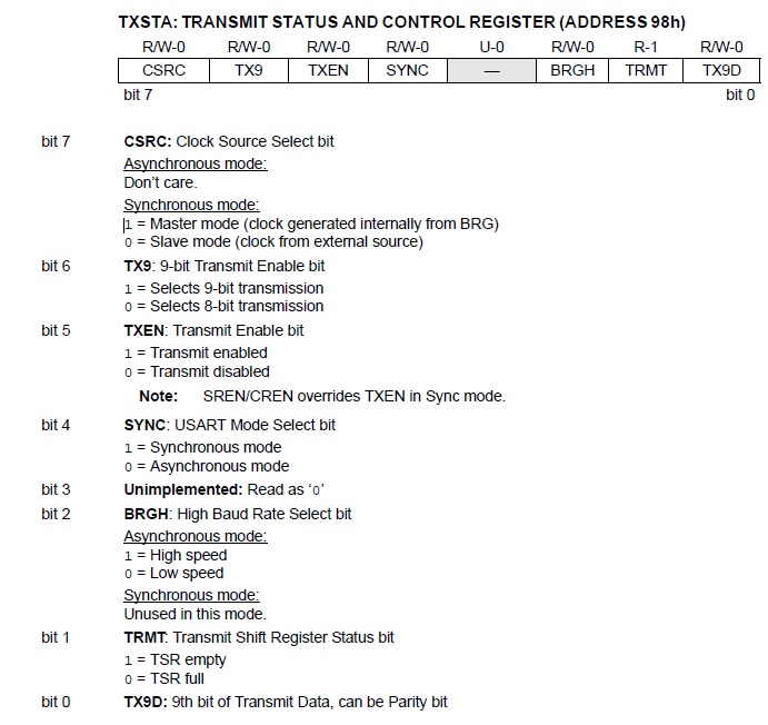
That’s a lot of bits to look at. For our purpose, we will only look at four bits from TXSTA and 1 bit from RCSTA.
Bit TXEN (bit 5) on TXSTA enables or disables transmission, SYNC ( bit 4) sets asynchronous or synchronous mode while BRGH (bit 2) sets the high-speed or low-speed mode. The formula used to compute the baud rate is different in high-speed or low-speed mode:

Here, X is the contents of the register SPBRG. So, for example, a baud rate of 9600 using a 4 MHz oscillator at high speed and asynchronous mode will have SPBRG = 25 as shown:
TRMT (bit 1) is a flag that sets if the data has been sent.
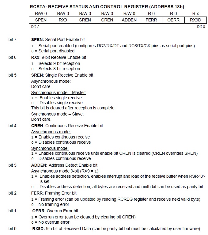
SPEN (bit 7) of the RCSTA register enables RC6 and RC7 as serial port pins. This is the bit you need to set to enable serial communication.
The data to be transmitted must be placed inside the TXREG register while the data received is placed inside the RCREG register.
We can simulate the serial communication using Proteus ISIS. Here is the schematic diagram:
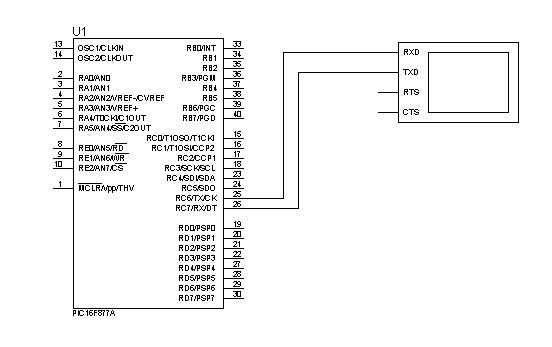
Note that other essential parts (like MCLR pullup, and oscillator) were not included in the diagram above.
Assembly Code for Transmitting Data
Here’s a PIC ASM code that sends a character ‘A’ out of the serial port of the PIC16F877A at a baud rate of 9600.
INCLUDE <P16F877A.INC>

	cblock 0x20
		char0
		COUNT1
		COUNT2
	endc

ORG 0x00
goto init

init	bsf STATUS, RP0   ;bank 1
	;---CONFIGURE SPBRG FOR DESIRED BAUD RATE
	movlw D'25'   	;baud rate =  9600bps
	movwf SPBRG   	;at 4MHZ
;---CONFIGURE TXSTA
	movlw B'00100100'
	movwf TXSTA
;Configures TXSTA as 8 bit transmission, transmit enabled, async mode, high speed baud rate
	bcf STATUS, RP0   ;bank 0
	movlw B'10000000'
	movwf RCSTA   	;enable serial port receive

	movlw 0x41
	movwf char0   	;put A (ascii code 0x41) character to char0 register

main	movf char0, W
	movwf TXREG   	;place the A character to TXREG
	goto wthere
	goto main

wthere	btfss TXSTA, TRMT ;check if TRMT is empty
    	goto wthere   	;if not, check again
	bcf STATUS, RP0   ;bank 0, if TRMT is empty then the character has been sent
	return

	end
You should see a single ‘A’ on the serial monitor.
The first part of the code above configures the serial port by making SPBRG = 25 (as per the calculations on our example calculation) and enabling transmit (at high speed, async) and receive ports via TXTSA and RCSTA.
The character to be sent is inside char0 and then moved to TXREG. Then we looped the program using btfss (on TRMT bit) to check if the character has been sent out.
Using XC8 to Send Serial Data
This is how the code above is implemented in XC8:
#define _XTAL_FREQ 4000000
#include <xc.h>

void main(){
        SPBRG = 25;
        TXSTA = 0b00100100; //transmit enable, async, high speed mode
        RCSTA = 0b10000000; //serial port enable

       while(TRMT){
               TXREG = ‘A’;
       }
}
How about sending strings? XC8 has a built-in library <stdio.h> for that. Apparently, you can use the printf() function to send strings out as long as you have a putch() function defined in your code.
Here’s how to send the string “hello world” via the serial port:
#define _XTAL_FREQ 4000000
#include <xc.h>
#include <stdio.h>

void main(){
        SPBRG = 25;
        TXSTA = 0b00100100; //transmit enable, async, high speed mode
        RCSTA = 0b10000000; //serial port enable

       printf(“Hello World!”);
}

void putch(char data){
        while(TRMT){
               TXREG = data;
        }
}
Receiving Data using Assembly
As mentioned, the received data through the serial port is stored in RCREG. When RCREG is read and emptied, a flag, RCIF is set.
RCIF is an interrupt flag that can be disabled using the RCIE bit in PIR1. However, we don’t need to set interrupts for the RCIF to trigger!
Here’s an assembly code that sets PORTB according to the value received from the serial port:
INCLUDE <P16F877A.INC>

org 0x00
goto start

start bsf STATUS, RP0
      movlw .25
      movwf SPBRG
      movlw 0x24
      movwf TXSTA
      clrf TRISB
      bcf STATUS, RP0
      movlw 0x90
      movwf RCSTA

main  btfss PIR1, RCIF
      goto main
      movf RCREG, W
      movwf PORTB
      goto main
Reception using C
Here’s how the code above looks like in XC8:
#define _XTAL_FREQ 4000000
#include <xc.h>

void main(void) {
   SPBRG = 25;
   TXEN=1;
   BRGH=1;
   SPEN=1;
   CREN=1;
   TRISB = 0;
   PORTB = 0;

   while(1){
       while(!RCIF);
       PORTB = RCREG;
       __delay_ms(100);
   }
}
Now how do we receive strings? Unfortunately, there isn't a direct library function for this one like printf() for displaying strings. I’ve created a routine that reads each character from a string and ends the string if a newline is received or the maximum number of characters (10 in this case) per string is received:
#define _XTAL_FREQ 4000000
#include <xc.h>
#include <stdio.h>

void putch(char data){                            //required for printf
    while(!TRMT);
    TXREG = data;
}
unsigned char getch(){                          //used to get each character
    while(!RCIF);
    return RCREG;
}

void getString(char *input, unsigned int length){
    for(int i=0;i<length;i++){
        input[i] = getch();                           //acquire each character until 10 chars are received
        if(input[i]==13)                              //or if newline is received
            break;
    }
    printf(“\rHello “);
    printf("%.10s",input);                        //print input string
}

void main(void) {
    SPBRG = 25;
    TXEN=1;
    BRGH=1;
    SPEN=1;
    CREN=1;
    TRISB = 0;
    PORTB = 0;

    unsigned char *buffer = (char *)0x20;   //assign to start of gen.purpose registers
    printf(“Enter your name: “);
    getString(&buffer, 10);                          //pass pointer address to function
 }
Here I declared a getch() function which is actually part of the <conio.h> library but is an empty stub (which means it’s useless unless you create one yourself). This getch() function passes each character received from the serial port to a character array input which is pointed by the buffer to start at 0x20, which is the starting address of the general purpose registers of the PIC16F877A.
While asynchronous communication is enough for most applications, there are instances when you need more transmission speed. The additional speed can be achieved if the timing between transmitter and receiver has been properly established, which is the case with synchronous serial communication protocols SPI and I2c. That is what we’ll cover next.

