
I always believed that the Arduino is a development board and is its microcontroller, the ATMega328 is the one meant to be featured in actual embedded systems projects. Nevertheless, no one can deny the advantages of boards like these as they make prototyping and debugging much easier. In this post, I will share how I built my own development board for the PIC16F877A microcontroller.
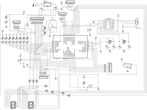
Development Board Schematic
There are actually two reasons why I build this dev board: for easier prototyping and for my engineering students. I’ve used PIC microcontrollers way before Arduinos arrived. My normal routine for building PIC projects is: simulate -> prototype on breadboard -> build final device. This has been working but I find it tiresome to assemble a PIC circuit on a breadboard from time to time.
With inspiration from the Arduino UNO’s schematic, I created this:
What's on the Board
The PIC16F877A development board, which I named SIMPic, has digital and analog ports, communication port for I2C and SPI and a servo motor port. I’ve also added eight LEDs directly connected to the digital port, an LM35 temperature sensor and two seven segment displays.
The digital port would enable me or my students to easily manipulate the GPIOs of the PIC16F877A. For this board, the digital port is wired to PORTB.
The analog port and the included LM35 temperature sensor will help during sensor reading as the port is connected to the AN pins of the PIC16F877A. I thought that including the LM35 is necessary for understanding the basics of analog to digital-conversion.
The seven segment displays would be helpful for teaching students how persistence-of-vision (POV) works. POV is a concept where your eyes are tricked that both displays are simultaneously on but in reality, they are alternately on. This technique reduces pin count and even cost as you don’t need a separate seven segment decoder.
But I believe the most significant part of this board is the USB port. Normally, flashing a program to a PIC board such as the PIC16F877A requires a separate hardware. I decided to add a USB to TTL converter IC like the CH340G which will enable me to load the program via USB. To make this possible, I must flash a bootloader to the PIC beforehand. A separate article on the bootloader will be written.
Development Board PCB
Here is now the PCB layout for the SIMPic:
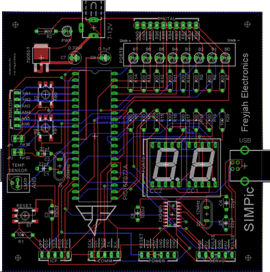
I positioned the ports on the edges for easy access. I also included a power port similar to that of the Arduino UNO. This power port contains an SMD 7805 for regulating the voltage. However, the board can be powered through the ICP or through the USB port.
What’s left is to build the PCB. I decided to commission JLCPCB to build the PCB because they are affordable and I have attested to their PCB quality before.
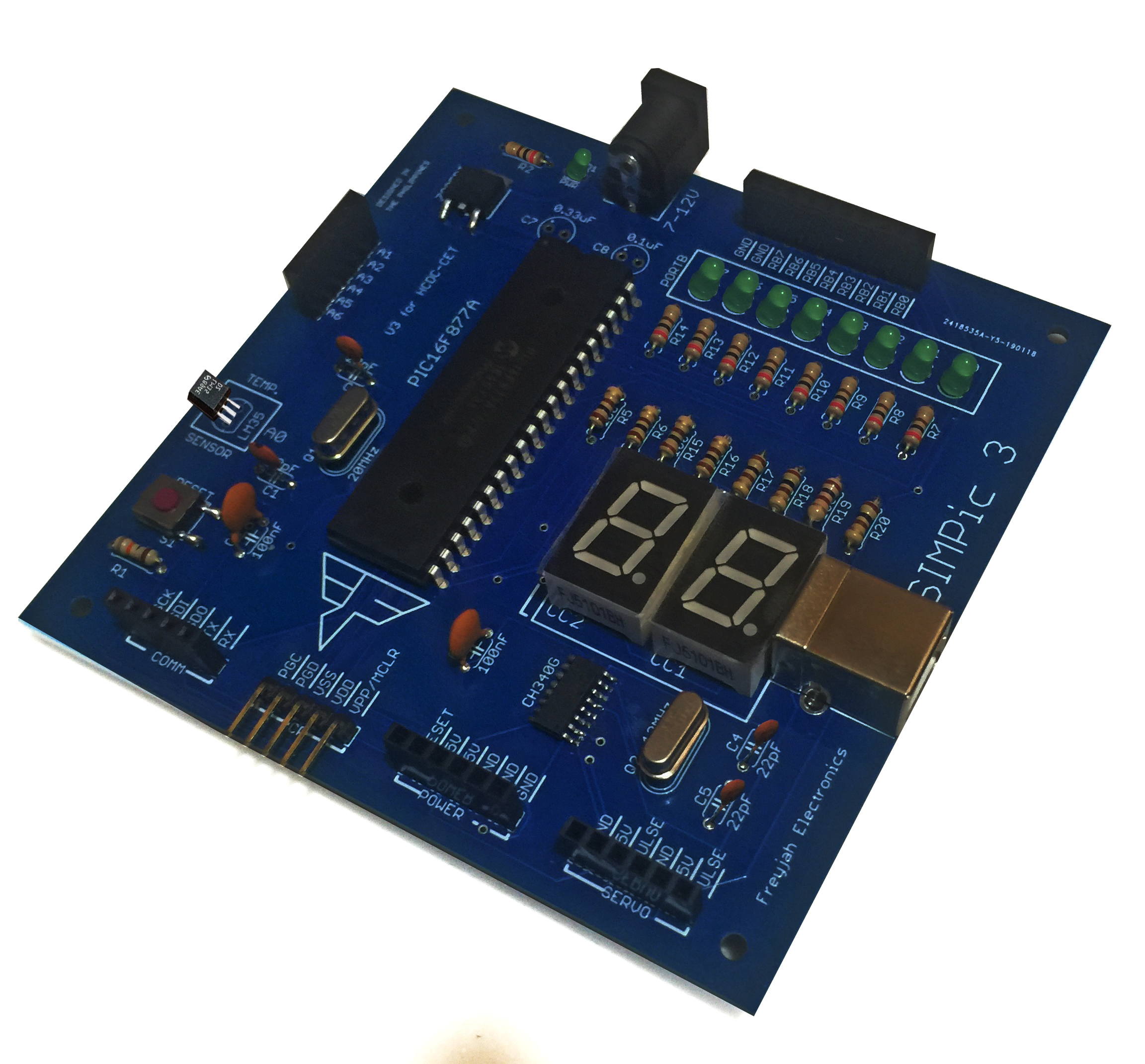
Here is now the assembled PICSim development board:

The board worked as expected! As for the bootloader, I got an idea from this page: http://www.etc.ugal.ro/cchiculita/software/picbootloader.htm . As mentioned, I will write a separate article on how I developed my own bootloader.
The next step for me is to create libraries for the XC8 compiler that is directly compatible to my SIMPic board. Also, I am looking to add more components to my board and maybe opt for SMD parts to reduce space. Stay tuned!

