
Relays in electronics are useful for controlling a high-power load using a smaller-power circuit. For example, an Arduino or PIC running on 5V, controlling a 240VAC light bulb, etc. This is what we have shown in our Arduino relay tutorial.
But did you know that there are different types of relays? That common box-like relay is called an electromechanical relay or EMR. And while EMRs are often enough to do the job, it’s far from perfect. This article will introduce you to a quieter alternative to EMRs: solid-state relays.
What is a Solid State Relay?
The term “solid-state” generally refers to semiconductor electronics such as transistors, diodes, etc. A solid state relay or SSR, features these electronic devices.
There are three common types of SSRs, grouped according to the electronic device inside it: BJT, MOSFET, or thyristor (SCR or TRIAC). Each of these operates through optoelectronics, i.e., the lower power side contains a light emitter that drives a light receiver on the high power side. The schematic below shows a TRIAC-based SSR.

Here, the input switch can be a port connected to a microcontroller. When this switch is closed, the low-power voltage source will turn on the LED, emitting a light that will drive the TRIAC. The TRIAC will start conducting and so the load will now receive power from the high voltage source.
When the input switch is opened, the LED will stop emitting light. However, since a TRIAC is on the output side, the load will continue to receive power until the voltage source reaches a current below the holding current of the TRIAC. Know more about how TRIACs operate.
SSRs have smaller footprints than EMRs, making them a good choice for tightly packed circuit boards. And because they don’t have any mechanical parts like the EMR, they are less susceptible to wear and tear and don’t make that “clicking” sound when driven. Moreover, the switching speed of SSRs is higher than EMRs.
SSR Module
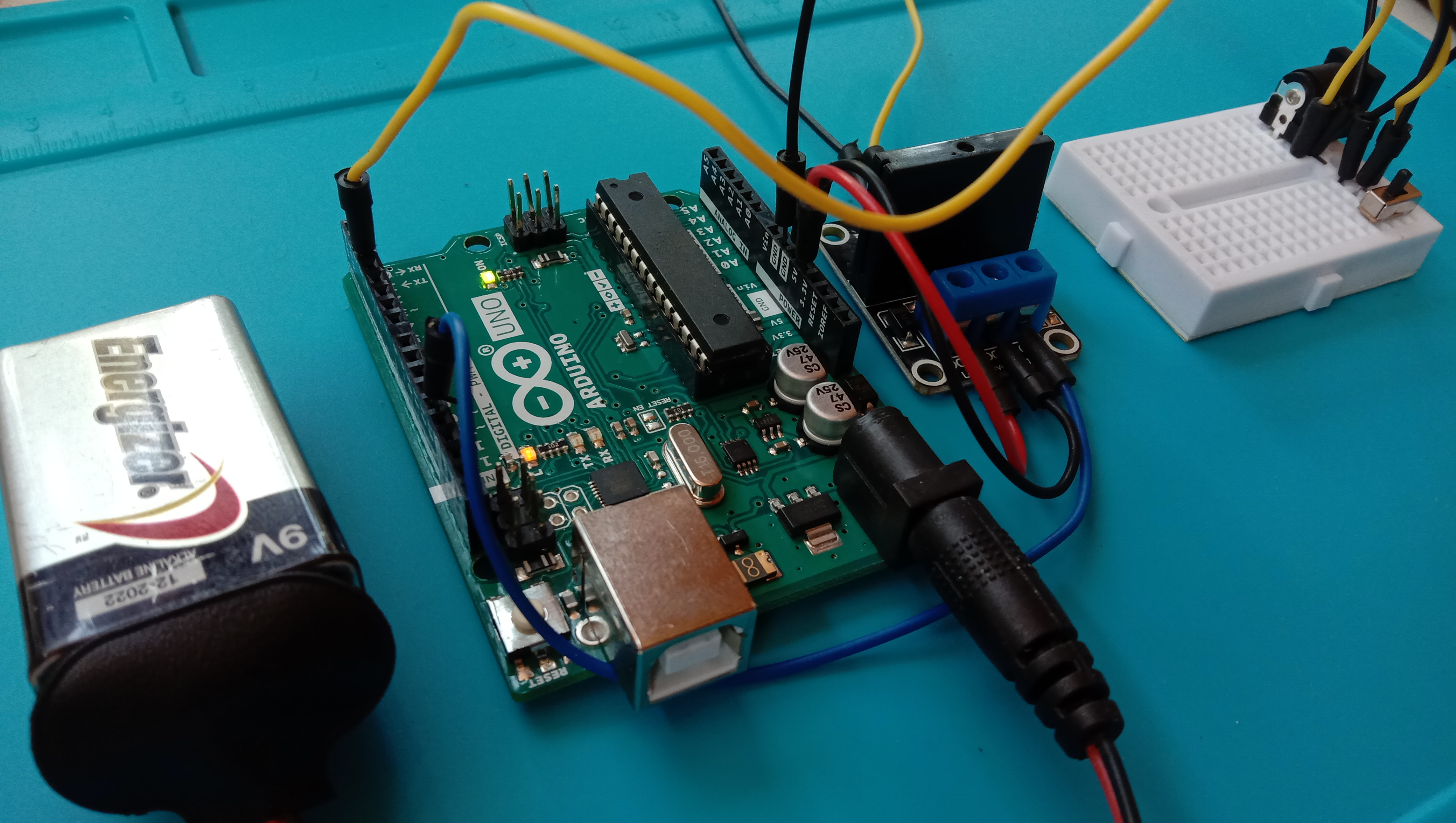
Much like any other devices nowadays, SSRs also come in easy-to-use modules as pictured.
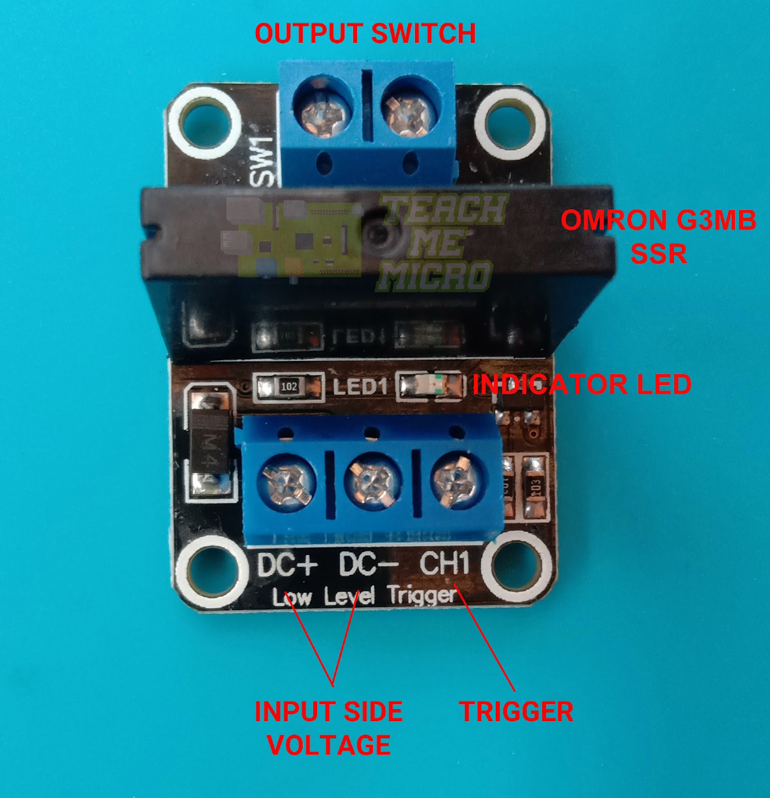
The input side of the module contains a three-pin screw terminal. Here, the input side voltage and trigger signal are attached. On the output side is a two-pin screw terminal where the load is attached.
To use the module, the DC+, and DC- pins are connected to the +5V and ground pins of the microcontroller, respectively. The CH1 pin is also connected to any digital pin of the microcontroller. The output terminal is then connected to the load in a similar way that a switch is connected. A helpful Fritzing diagram is shown below:
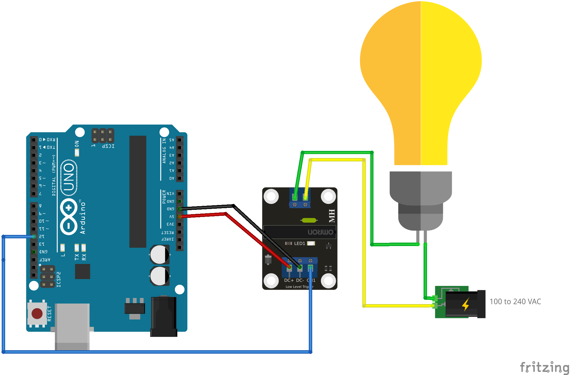
Note that the power for the Arduino UNO is omitted. Here, the trigger input of the SSR module is connected to digital pin 12. When this pin goes high, the relay is turned on and the bulb will light up. When the pin goes low, the bulb will turn off when the high voltage source reaches below the holding current. For this particular SSR, the bulb should turn off after half of the AC cycle with a tolerance of about 1 millisecond. That’s about 7 to 10 ms.
WiFi Switch using Solid State Relay
A good example project for the SSR module is a WiFi switch to a 240VAC light bulb. We will replace the Arduino UNO on the diagram above with an ESP8266-based board like the WeMos D1 Mini. The WeMos D1 Mini will then host a web page that a user can access via WiFi. The user can turn on or off the light bulb using any device connected to the WiFi access point of the WeMos D1 Mini.
Here is the Fritzing diagram for the WiFi switch:
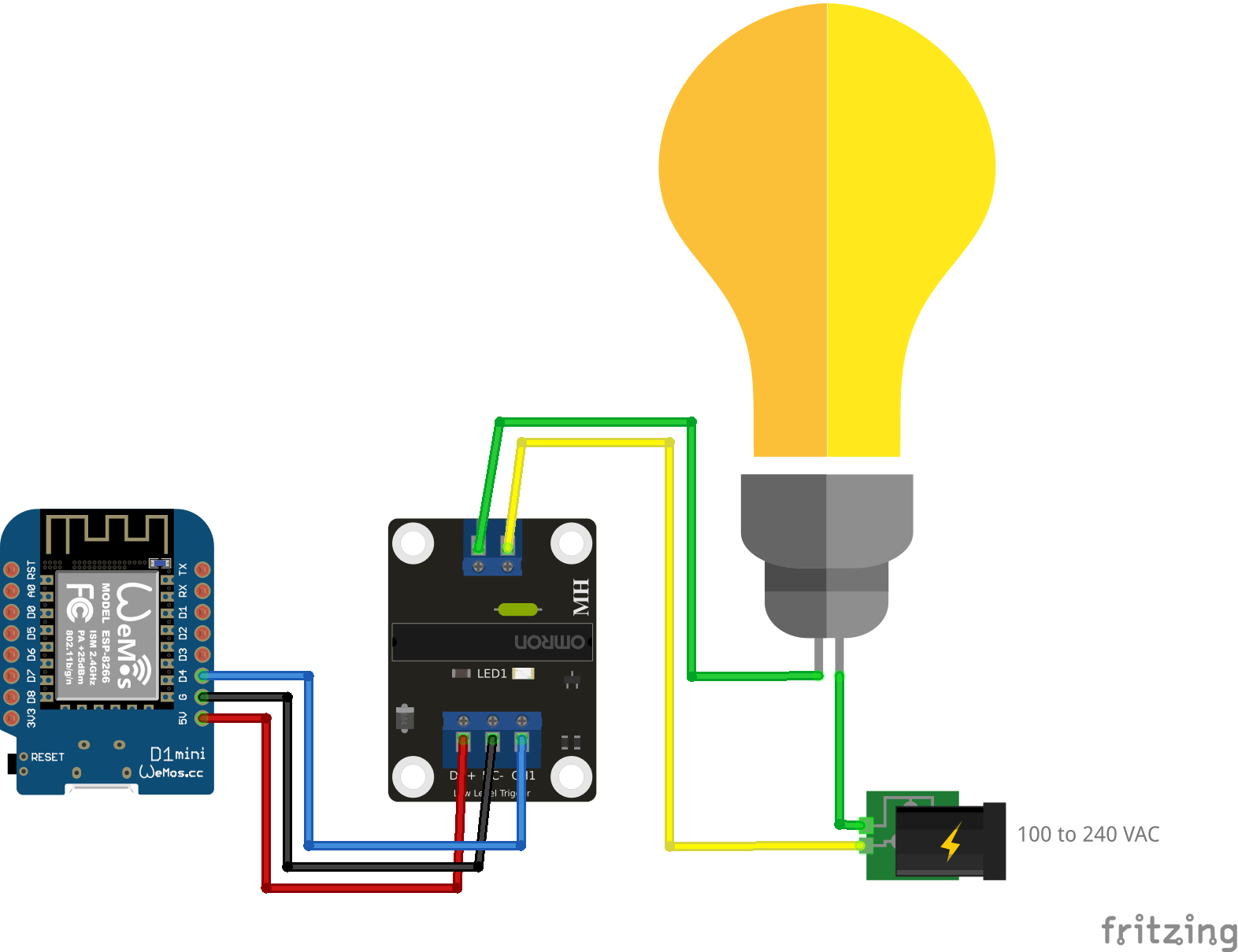
Again, power to the WeMos D1 Mini here is omitted. You can use a micro USB cable to power the WeMos D1 Mini through your computer or use appropriate batteries.
And here is the sketch. Read how to set up WeMos D1 Mini first before compiling this sketch.
#include <ESP8266WiFi.h>
#include <WiFiClient.h>
#include <ESP8266WebServer.h>
// Replace with your network credentials
const char* ssid = "<YOUR WIFI SSID>";
const char* password = "<YOUR WIFI PASSWORD>";
ESP8266WebServer server(80); //instantiate server at port 80 (http port)
String page = "";
int loadPin = D4;
void setup(void){
//the HTML of the web page
page = "<h1>WiFi Switch</h1><p><a href=\"LEDOn\"><button>ON</button></a> <a href=\"LEDOff\"><button>OFF</button></a></p>";
//make the LED pin output and initially turned off
pinMode(loadPin, OUTPUT);
digitalWrite(loadPin, LOW);
delay(1000);
Serial.begin(115200);
WiFi.softAP(ssid, password); //begin WiFi connection
Serial.println("");
// Wait for connection
while (WiFi.status() != WL_CONNECTED) {
delay(500);
Serial.print(".");
}
Serial.println("");
Serial.print("Connected to ");
Serial.println(ssid);
Serial.print("IP address: ");
Serial.println(WiFi.softAPIP());
server.on("/", [](){
server.send(200, "text/html", page);
});
server.on("/LEDOn", [](){
server.send(200, "text/html", page);
digitalWrite(loadPin, HIGH);
delay(1000);
});
server.on("/LEDOff", [](){
server.send(200, "text/html", page);
digitalWrite(loadPin, LOW);
delay(1000);
});
server.begin();
Serial.println("Web server started!");
}
void loop(void){
server.handleClient();
}
When this sketch has been uploaded, open the serial monitor to view the IP address of the WeMos D1 Mini. Next, use a smartphone or computer and turn on your WiFi. The SSID of the WeMos D1 Mini should appear. Connect to it using the password you specified on the sketch.
Then, open your preferred web browser and type the IP address of the WeMos D1 Mini on the address bar. Two switches should appear on the web page.
Video tutorials and demonstration to follow!
Was this article helpful? Kindly drop a comment below!

