
This project is a stepper motor controller featuring the PIC16F877A microcontroller and coded using XC8. The controller has three control buttons: start, stop, forward and reverse. The project was created with a six-wire unipolar stepper motor in mind but may work with other stepper motors with some modifications.
Introduction
A stepper motor requires pulses in specific pattern to move or “step”. Generally, there are three ways to move a stepper motor.
- Half-step - a single wire is set high while the others are set low. The pulsed wires are alternated to make a full revolution
- Full-step - two wires are set high simultaneously while the others are set low. The paired wires are alternated to make a full revolution.
- Microstepping - half-step and full-step patterns are combined to make finer movements.
This project uses microstepping as it is the most commonly used stepping method.
Materials Needed
- PIC16F877A
- Unipolar 6-wire Stepper Motor
- 5 x SPST pushbuttons
- 4 x BC547 NPN transistor
- 5 x 10k 1/4 W resistor
- 4 MHz crystal
- 2 x 22pF ceramic capacitor
Schematic Diagram
The schematic diagram for the stepper motor controller is shown below:

Basically, each of the wires of the stepper motor is connected to a transistor switch to allow more current through the motor. A pulse from the microcontroller turns on a transistor and effectively shorts the connected wire to ground. Since the common pin is tied to the positive supply (which is separate from the microcontroller supply), the microcontroller pin must be low to make a stepper motor wire high.
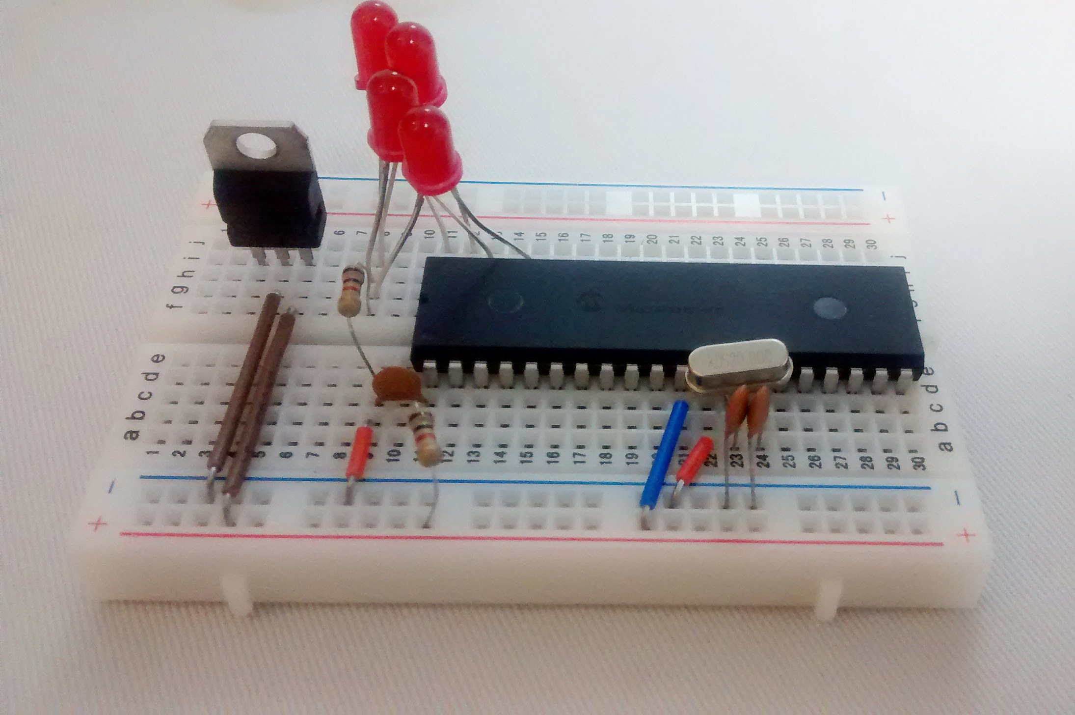
I’ve included LEDs to have a visual representation of the stepping patterns. Obviously, omitting them will not have any adverse effect on the project’s performance.
Lastly, the choice of transistor depends on the current draw of your chosen stepper motor. For larger stepper motors, I suggest using darlington pairs.
Code
/*
 * File:   stepper.c
 * Author: Roland Pelayo
 * For Stepper Motor Controller Project published on Teach Me Microcontrollers!
 * Created on April 4, 2018, 1:28 PM
 */
#pragma config FOSC = XT // Oscillator Selection bits (XT oscillator)
#pragma config WDTE = OFF // Watchdog Timer Enable bit (WDT disabled)
#pragma config PWRTE = OFF // Power-up Timer Enable bit (PWRT disabled)
#pragma config BOREN = OFF // Brown-out Reset Enable bit (BOR disabled)
#pragma config LVP = OFF // Low-Voltage (Single-Supply) In-Circuit Serial Programming Enable bit (RB3 is digital I/O, HV on MCLR must be used for programming)
#pragma config CPD = OFF // Data EEPROM Memory Code Protection bit (Data EEPROM code protection off)
#pragma config WRT = OFF // Flash Program Memory Write Enable bits (Write protection off; all program memory may be written to by EECON control)
#pragma config CP = OFF // Flash Program Memory Code Protection bit (Code protection off)

#define _XTAL_FREQ 4000000
#include <xc.h>

int mode;         //1 = forward ; 0 = reverse
int ready;        //1 = stop ; 0 = start
int dummy;

//Main Routine
void main(void) {

    ready = 1;       //motor is stopped by default;
    TRISB = 0xF0;    //RB4, RB5, RB6, RB7 pins are input
    TRISD = 0;       //all PORTD pins are output
    INTCON = 0x88;   //global interrupts enabled, RB port change interrupt enabled
    PORTB = 0;       //initialize PORTB pins to cleared
    PORTD = 0;       //initialize PORTD pins to cleared

    while(1){
        if(ready==0){
            if(mode==1){          //forward direction
                PORTD = 0b11110110;
                __delay_ms(500);
                PORTD = 0b11111110;
                __delay_ms(500);
                PORTD = 0b11111100;
                __delay_ms(500);
                PORTD = 0b11111101;
                __delay_ms(500);
                PORTD = 0b11111001;
                __delay_ms(500);
                PORTD = 0b11111011;
                __delay_ms(500);
                PORTD = 0b11110011;
                __delay_ms(500);
            }
            if(mode==0){        //reverse direction
                PORTD = 0b11110111;
                __delay_ms(500);
                PORTD = 0b11110011;
                __delay_ms(500);
                PORTD = 0b11111011;
                __delay_ms(500);
                PORTD = 0b11111001;
                __delay_ms(500);
                PORTD = 0b11111101;
                __delay_ms(500);
                PORTD = 0b11111100;
                __delay_ms(500);
                PORTD = 0b11111110;
                __delay_ms(500);
                PORTD = 0b11110110;
                __delay_ms(500);
            }
      }
    }
    return;
}

//Interrupt Service Routine
void interrupt isr(void){
    if(RBIF){           //check RB change interrupt flag if triggered
      dummy = PORTB;    //read PORTB to clear mismatch condition
      if(!RB6){         //stop button pressed?
          ready = 1;
      }else if(!RB7){   //start button pressed?
          ready = 0;
      }else if(!RB5){   //forward button pressed?
          mode = 0;
      }else if(!RB4){   //reverse button pressed?
          mode = 1;
      }else{;}
    }
    RBIF = 0;
}
The four buttons are purposely tied to RB4, RB5, RB6 and RB7 because I wanted to use RB change interrupt. This allows me to change the stepper motor behavior even if the motor is currently turning. Using an interrupt with buttons also diminishes debounce problems. If you’re having problems understanding the code, kindly refer to my interrupt tutorial.

