

You can drive an LED on or off using a microcontroller like Arduino or PIC. There’s no problem there because the 20 mA or so current from the pins is enough. You can’t drive loads that require much more current like a motor. This is where the L298N motor controller comes in.
Introduction
The L298N motor controller follows the H-bridge configuration, which is handy when controlling the direction of rotation of a DC motor. An H-bridge schematic looks like this:
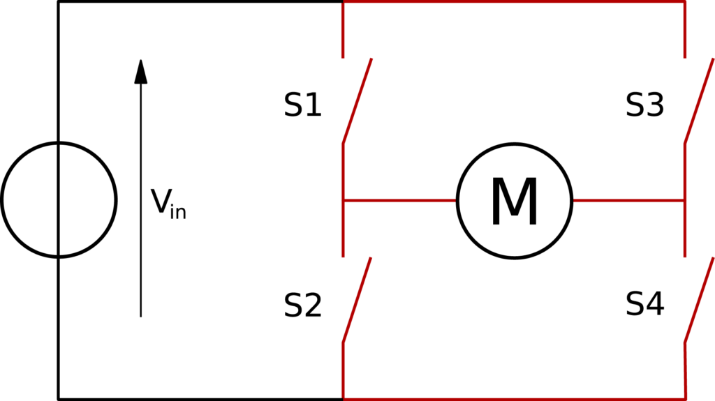
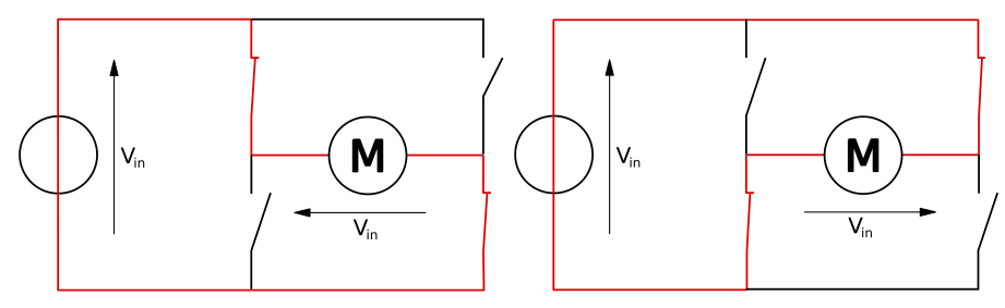
Here, the motor rotates in the direction dictated by the switches. When S1 and S4 are on, the left motor terminal is more positive than the right terminal, and the motor rotates in a certain direction. On the other hand, when S2 and S3 are on, the right motor terminal is more positive than the left motor terminal, making the motor rotate in the other direction.
The other benefit of using an H-bridge is that you can provide a separate power supply to the motors. This is very significant, especially when using an Arduino board where the 5V power source is simply not enough for two DC motors.
The L298N IC
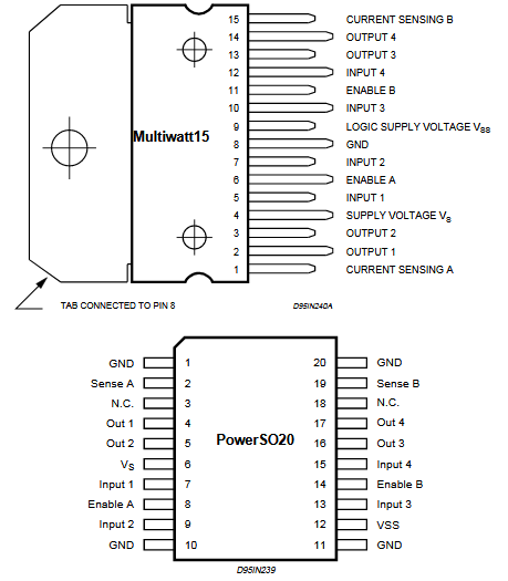
The L298N is an integrated circuit that follows the H-bridge concept. It comes in two IC packages: MultiWatt15 and PowerSO20. Here are the pinouts for each package:
This IC drives two motors through two channels, A and B. For example, if a motor is using channel A, its terminals must be connected to pins Out 1 and Out 2. The Enable A pin must be high to turn on the motor. To drive a motor to a direction, say, clockwise, the pin Input 1 must be high while the pin Input 2 must be low. To drive the motor counterclockwise, the pin Input 1 is low while the pin Input 2 is high.
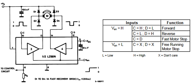
The diagram above shows an example diagram for using the L298N to drive one DC motor.
Here are the IC's ratings:
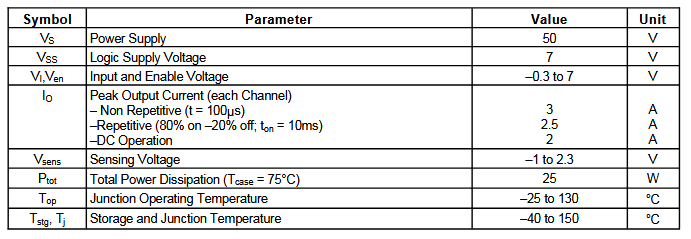
The most notable feature here is its high power supply although its input pins follow lower voltage levels. This means you can power high voltage motors while controlling them with microcontrollers.
More information about the L298N IC is found on its datasheet.
For this tutorial, we will be focusing more on the L298N breakout board.
The L298N Motor Controller Board
As already mentioned, the L298N has four inputs corresponding to the four switches in the H-bridge diagram above. All you need to do is apply signals to the inputs to make the motor(s) rotate to a certain direction.
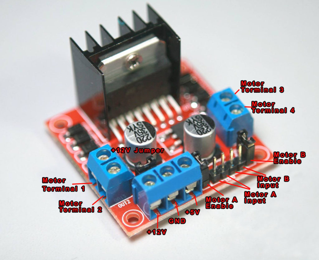
Using a breakout board is easier for prototyping compared to using the IC.
The controller board, shown above, has +12V and +5V terminals. The +12V pin is where the motor power is attached. This pin can accept voltages from +7VDC to +35VDC.
Important note: remove the +12V jumper shown if you are using powers higher than +12V.
When the +12V jumper is attached, the on-board voltage regulator is now enabled, and you can source +5V from the +5V terminal. This means the +5V terminal is not for powering the board but for connecting a device, say Arduino, that needs a 5V source.
You have Motor A inputs and Motor B inputs. These connect to the microcontroller. The motor terminals connect to Motor Terminals 1, 2, 3, 4. Specifically, motor A connects to terminals 1 and 2 while Motor B connects to terminals 3 and 4.
There are also two other jumpers on the board, as shown. Remove these jumpers if you are using DC motors and keep it for stepper motors. Speed control for Motor A and Motor B is achieved via PWM on these pins. More on that later.
Connecting a DC Motor to the L298N Board
Here is a wiring diagram for connecting two DC motors to the L298N driver board.
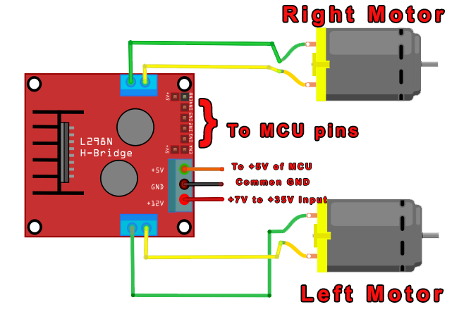
Using the L298N is straightforward. If you want the left motor to rotate in one direction, apply a high pulse to IN1 and a low pulse to IN2. To reverse the direction, reverse the pulses to IN1 and IN2. The same applies to the right motor.
Here’s a table that summarizes the pins and corresponding motor direction. This assumes you are following the same Fritzing diagram above.
| IN1 | IN2 | IN3 | IN4 | Direction |
| 0 | 0 | 0 | 0 | Stop |
| 1 | 0 | 1 | 0 | Forward |
| 0 | 1 | 0 | 1 | Reverse |
| 0 | 1 | 1 | 0 | Left |
| 1 | 0 | 0 | 1 | Right |
Speed Control?
Speed control is also possible with the L298N motor driver. All you need is to feed PWM signals to the motor-enable pins. The speed of the motor will vary according to the width of the pulses. The wider the pulses, the faster the motor rotates. How fast the motor rotates for a given pulse width will vary from motor to motor even if they look the same. Thus, the actual pulse width must be derived through experiment.
Using the L298N with Arduino
An example diagram for connecting the L298N motor controller board to an Arduino is shown:
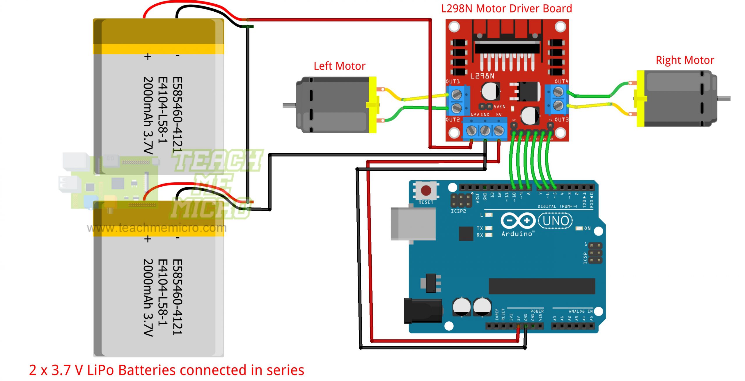
You can attach the control pins to any digital (or even analog) pins. However, for motor speed control, the motor enable pins must be attached to a PWM-enabled pin. Here you see that the motor enable pins connect to pin 10 and pin 5, both of which are PWM pins.
Here’s an example Arduino sketch utilizing the diagram above:
//Motor Connections
//Change this if you wish to use another diagram
#define EnA 10
#define EnB 5
#define In1 9
#define In2 8
#define In3 7
#define In4 6


void setup()
{
  // All motor control pins are outputs
  pinMode(EnA, OUTPUT);
  pinMode(EnB, OUTPUT);
  pinMode(In1, OUTPUT);
  pinMode(In2, OUTPUT);
  pinMode(In3, OUTPUT);
  pinMode(In4, OUTPUT);
}
void goStraight()   //run both motors in the same direction
{
  // turn on motor A
  digitalWrite(In1, HIGH);
  digitalWrite(In2, LOW);
  // set speed to 150 out 255
  analogWrite(EnA, 200);
  // turn on motor B
  digitalWrite(In3, HIGH);
  digitalWrite(In4, LOW);
  // set speed to 150 out 255
  analogWrite(EnB, 200);
  delay(2000);
  // now turn off motors
  digitalWrite(In1, LOW);
  digitalWrite(In2, LOW);
  digitalWrite(In3, LOW);
  digitalWrite(In4, LOW);
}
void loop()
{
  goStraight();
  delay(1000);
}
You can modify this sketch to include a function for going backward, turning left, and turning right. Just follow the table above.
Using the L298N with PIC
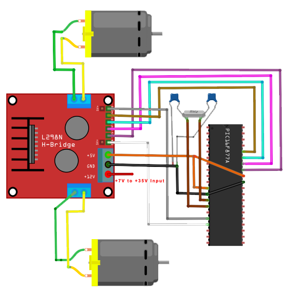
You can also use a PIC microcontroller with the L298N motor controller board. Here is an example diagram using the PIC16F877A:
And here’s an XC8 code that does the same as the Arduino sketch above:
#define _XTAL_FREQ 4000000
#include
#include "pwm.h"


void goStraight(){
    //turn on motor A
    PORTBbits.RB0 = 1;
    PORTBbits.RB1 = 0;
    startPWM(1);     //pulse motor enable A
    //turn on motor B
    PORTBbits.RB2 = 1;
    PORTBbits.RB3 = 0;
    startPWM(2);     //pulse motor enable B
    __delay_ms(2000);
    PORTBbits.RB0 = 0;
    PORTBbits.RB1 = 0;
    PORTBbits.RB2 = 0;
    PORTBbits.RB3 = 0;

}
void main(void) {

    TRISBbits.TRISB0 = 0;   //IN1
    TRISBbits.TRISB1 = 0;   //IN2
    TRISBbits.TRISB2 = 0;   //IN3
    TRISBbits.TRISB3 = 0;   //IN4
    initPWM(500, 50, 1);   //initialize PWM at 50% duty cycle, 500 Hz
    while(1){
        goStraight();
        __delay_ms(1000);
    }

    return;
}
You might need to read my PWM tutorial for PICs to understand the code above.
I hope you find this tutorial helpful!

