
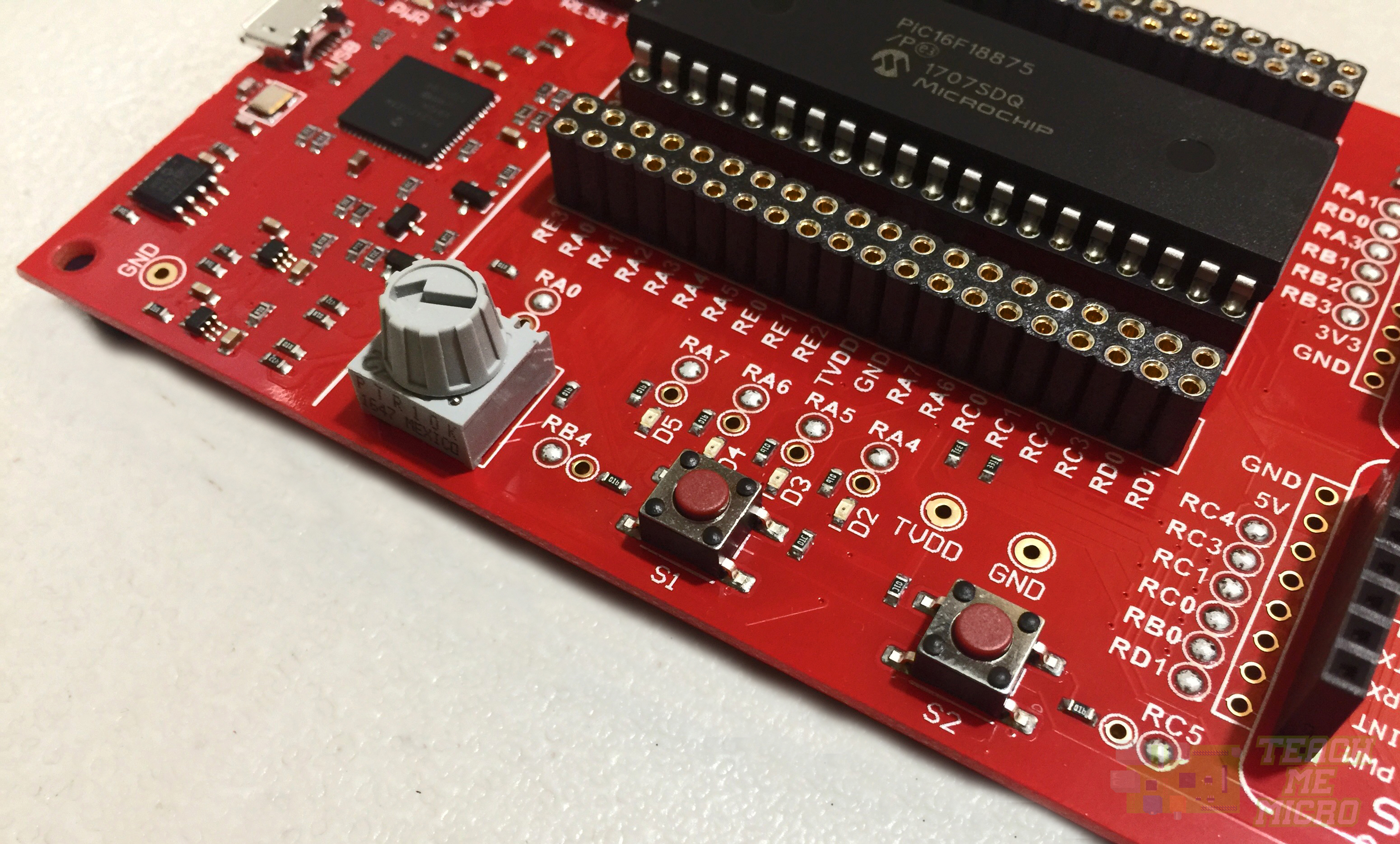
Last time, I showed how to get started with Microchip's Curiosity HPC board. I will now explore the use of the included buttons and LEDs on this microcontroller board.
When using development boards for the first time, it's always a good idea to look at its datasheet first. The Curiosity HPC has four properly-labeled LEDs. But I needed to make sure if they were active low or high. Also, I needed to know if the buttons are normally high or normally low.
The schematic of the development board shows this:
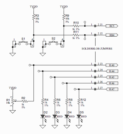
So I've confirmed two things: the LEDs will turn on when I set their corresponding pins and the buttons are normally high.
Controlling the On-Board LEDs
Now I will try to create strobe lights out of the four LEDs on the board. With the older PIC16F877A, I only need to manipulate TRIS and PORT registers to control the output pins of that PIC. However, for newer PICs like the PIC16F18875 on the Curiosity HPC, there is now a LAT short for "latch" register.
Manipulating any pin of the PIC requires the use of the LAT or PORT registers. According to the datasheet, writing a value to a PORT actually writes the value into its LAT register. Meanwhile, reading from a PORT returns a value that is the actual state of the I/O pins. This is a consequence of the pins following the read-modify-write operation: when writing to a PORT, the current states of the pins of that PORT are READ, the read values MODIFIED, and is now WRITTEN to the corresponding LAT register.
The existence of PORT and LAT registers is somewhat vague but I have come to understand it like this: write to LAT, read from PORT.
Another peculiarity is that all pins are now analog by default. The corresponding ANSEL bits should be "0" to make a pin digital. For example, writing "0" to ANSA4 makes RA4 digital.
So let's say we want to flash led D2 which is wired to RA4, this is now the code:
#define _XTAL_FREQ 4000000

#include <xc.h>

void main(void) {
    TRISA4 = 0;           //Make RA4 output
    ANSA4 = 0;            //and a digital I/O pin

    while(1){            //Make the flashing endless
        LATA4 = 1;       //Set RA4
        __delay_ms(500); //Half a second delay
        LATA4 = 0;       //Clear RA4
        __delay_ms(500); //Another half-second delay
    }
    return;
}
Here, line 7 is how you would make a pin digital. Writing "1" to LATA4 turns on the LED on RA4 and writing "0" turns it off.
I tried changing LATA4 to RA4 and the LED still flashed. I believe the difference between LAT and PORT will not be obvious here because I only wrote to a port, not read it. What you write to RA4 also becomes the value of LATA4.
Now for the strobe light code, I only needed to modify the code above and now include the rest of the LED pins:
#define _XTAL_FREQ 4000000

#include <xc.h>

void main(void) {
    TRISA4 = 0;
    TRISA5 = 0;
    TRISA6 = 0;
    TRISA7 = 0;
    ANSA4 = 0;
    ANSA5 = 0;
    ANSA6 = 0;
    ANSA7 = 0;

    while(1){
        LATA = 0b10000000;
        __delay_ms(500);
        LATA = 0b01000000;
        __delay_ms(500);
        LATA = 0b00100000;
        __delay_ms(500);
        LATA = 0b00010000;
        __delay_ms(500);
    }
    return;
}
Something's Wrong with RA7
The code above flashes the LEDs EXCEPT for RA7! I browsed the PIC16F18875 datasheet and found this:
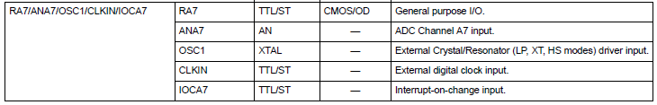
RA7 is also a digital clock input pin (CLKIN) as seen. Based on experience, CLKIN pins tend to be current sinks by default. This may be the reason why RA7 wasn't able to drive the on-board LED.
More datasheet reading led me to this:
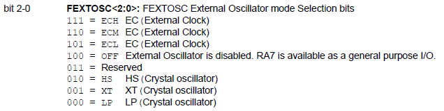
This tells me that if FEXTOSC is set to OFF, then I can now use RA7 just like any other I/O pin.
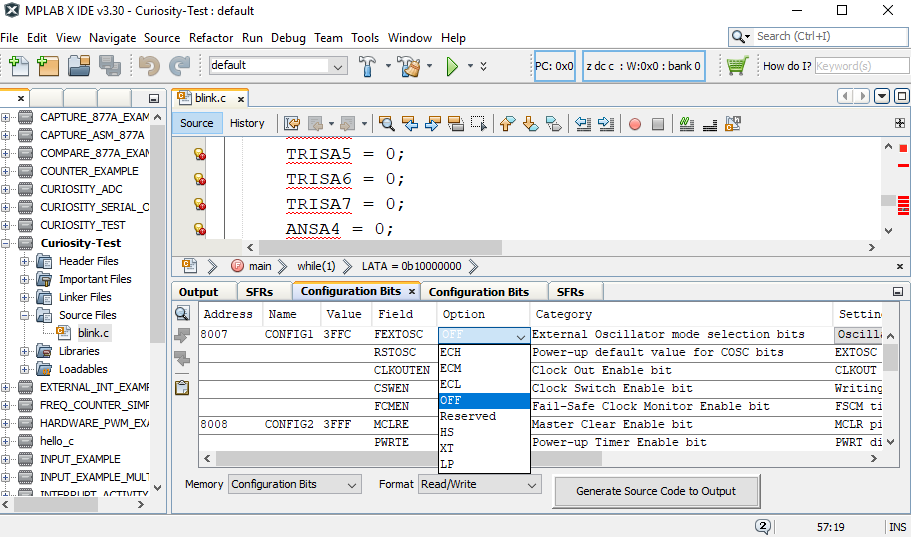
FEXTOSC is in fact part of the configuration word for the microcontroller. To manipulate it, I needed to view the configuration bits via Run > Configuration Bits. The Configuration Bits window now appears at the bottom:
The first row of the field shows FEXTOSC. I just needed to change this to OFF and click the "Generate Source Code to Output". The Config Bits Source will now appear:
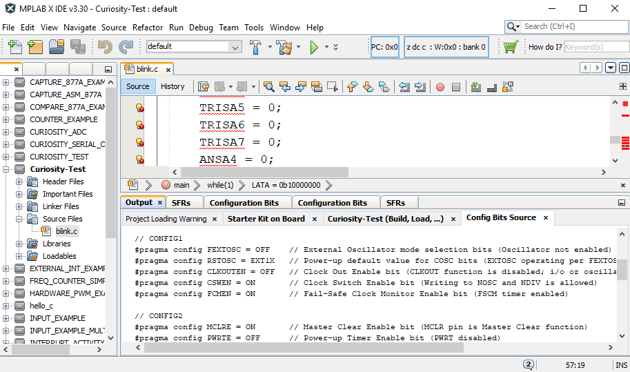
I just then copied this source to my code (right after the #insert <xc.h> line).
After that, RA7 is now flashing along with the other LEDs.
Using the On-board Buttons
Now that I managed to control the on-board LEDs on the Curiosity HPC, it's time to use the two user buttons. I believe this is now a better setting for describing the difference between PORT and LAT.
Consider the code below:
void main(void) {
    TRISA4 = 0;
    TRISC5 = 1;
    ANSELA = 0;
    ANSELC = 0;

    LATC5 = 0;
    while(1){
       if(LATC5 ==  1){
           RA4 = 1;
       }else{
           RA4 = 0;
       }
    }
    return;
}
With this code, RA4 stays on regardless if S2 is pressed or not. Why? because I wrote a "0" to LATC5 and unless I read RC5, that pin will remain "0". LATC5 will never look at the current state of pin RC5. Hence, RA4 will also remain 0.
Now if you tweak the code above to this:
void main(void) {
    TRISA4 = 0;
    TRISC5 = 1;
    ANSELA = 0;
    ANSELC = 0;

    RC5 = 0;
    while(1){
       if(RC5 ==  1){
           RA4 = 1;
       }else{
           RA4 = 0;
       }
    }
    return;
}
This time, RA4 will turn on or off if ever I press or depress S2. Even though I wrote "0" to RC5, this bit will always be equal to the current state of the pin. This is how I understood LAT and PORT.
So much for that. Now I will modify my LED strobe code above so that the strobe will change direction if I press S1 or S2. Here's my code:
void main(void) {
    TRISA4 = 0;
    TRISA5 = 0;
    TRISA6 = 0;
    TRISA7 = 0;
    TRISB4 = 1;
    TRISC5 = 1;
    ANSA4 = 0;
    ANSA5 = 0;
    ANSA6 = 0;
    ANSA7 = 0;
    ANSB4 = 0;
    ANSC5 = 0;

    while(1){
        if(RB4==0){
            LATA = 0b10000000;
            __delay_ms(500);
            LATA = 0b01000000;
            __delay_ms(500);
            LATA = 0b00100000;
            __delay_ms(500);
            LATA = 0b00010000;
            __delay_ms(500);
        }else if(RC5==0){
            LATA = 0b00010001;
            __delay_ms(500);
            LATA = 0b00100000;
            __delay_ms(500);
            LATA = 0b01000000;
            __delay_ms(500);
            LATA = 0b10000000;
            __delay_ms(500);
        }else{
            LATA = 0x00;
            __delay_ms(500);
            LATA = 0xF0;
            __delay_ms(500);
        }

    }
    return;
}
And here's the result of the code above (BTW, sorry for the potato quality gif):
That's it for using the user LEDs and buttons on the Curiosity HPC board. In my next article, I'll try to explore the mikroBUS slots.

