
A water level sensor is a simple device used to measure the level and volume of water inside a container. This tutorial shows you how to use a water level sensor with microcontrollers like an Arduino or PIC.
Introduction
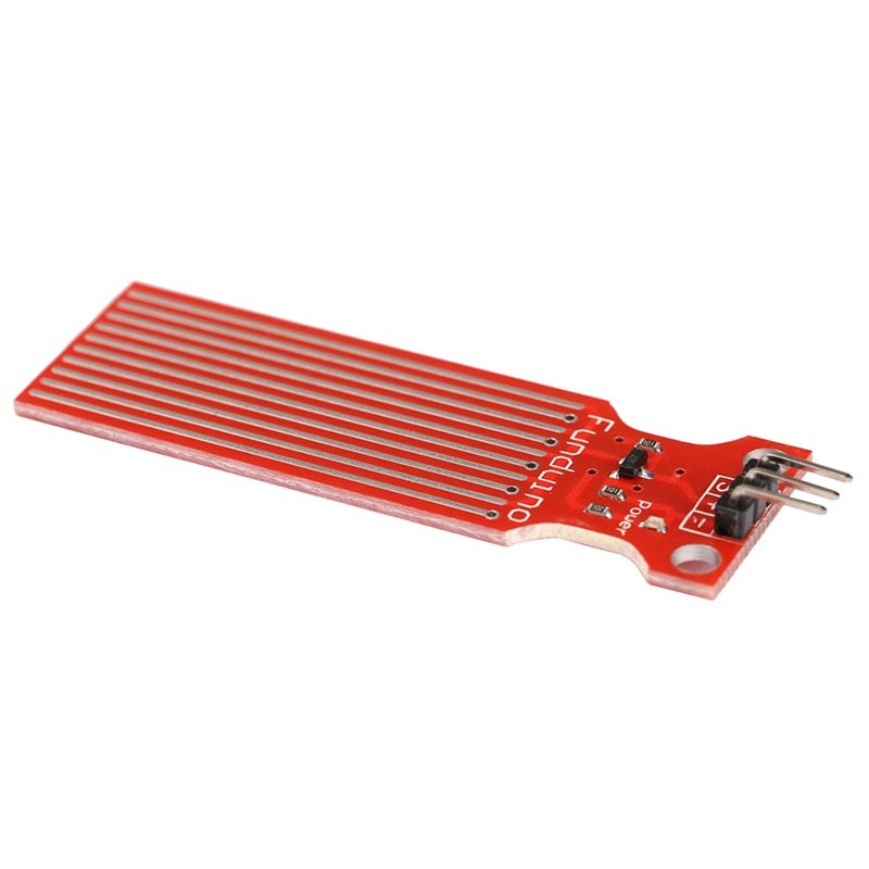
Water level sensors range from educational to industrial. The most common and frequently seen in stores is this one:
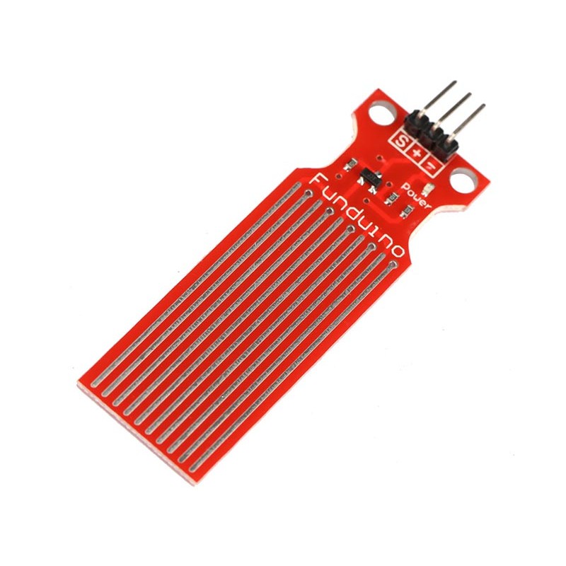
This is a conductive-type water level sensor, where the change in resistance of parallel wires over varying depths of water is converted to voltage. This is not ideal for high precision water level monitoring and is only suitable for hobby projects.
The module has three pins: + (5V), - (GND), and S (Signal). The S pin outputs voltage corresponding to water level.
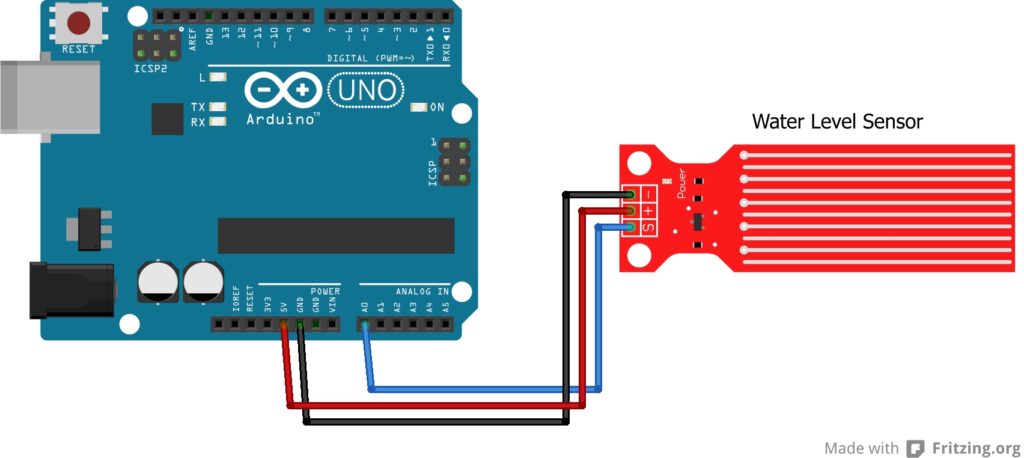
Wiring Diagram
Connecting the water level sensor to a microcontroller is easy: just connect the S pin to any analog pin. Of course, you must connect the and the + and - pin to power and ground. Here's an example wiring diagram with an Arduino:
Arduino Sketch
The sketch for the water level sensor is also simple:
void setup()
{
	Serial.begin(9600);
}

void loop()
{
	Serial.println(analogRead(A0));
	delay(100);
}
This sketch will display varying numbers on the serial monitor as you vary the depth of the water. You cannot display the actual levels unless you do some actual tests. I suggest you use a calibrated container like this one:

Fill up this container with liquid up to each calibration. Then place the water level sensor, open serial monitor and record the number. Add more water reaching each label on the container then record the number again. Continue doing this until you've filled the container.
[the_ad id="3059"]
PIC XC8 Code
To use this water level sensor with a PIC, we can use the code I created in my PIC ADC tutorial:
#include  // include processor files - each processor file is guarded.
#include
#include
#include
void Serial_init(const long int baudrate){
    BRGH = 1;
    unsigned int x;
    x = (_XTAL_FREQ /(baudrate*16))-1;
    SPBRG = x;
    SYNC = 0;
    SPEN = 1;
    TRISC7 = 1;
    TRISC6 = 1;
    CREN = 1;
    TXEN = 1;
}
void putch(char data) {
    while(!TRMT);
    TXREG = data;
}
unsigned int ADC_read(int channel){
    ADFM = 1; //results right justified
    ADCS0 = 0; //conversion speed = 4*Tosc
    ADCS1 = 0;
    ADCS2 = 1;
    ADCON0bits.CHS = channel;
    ADON = 1; //turn on ADC
    __delay_ms(1);
    GO_DONE = 1;
    while(ADCON0bits.GO_DONE == 1);
    unsigned int adval = (ADRESH << 8) + ADRESL; //ex 1002
    return adval;
}
void main(void) {
    Serial_init(9600);
    int adval = ADC_read(0); //read analog signal at channel 0
    char buf[5];             //buffer to hold conversion result from integer to string
    itoa(buf, adval, 10);    //convert integer ADC result to string and store to buf
    printf("\rValue: %s\n",buf);  //print through Serial port
    __delay_ms(10);
}
It is assumed that the S pin of the sensor is attached to channel AN0 of the PIC's ADC. Similar to the Arduino example, you still need to do tests and recording to acquire the levels in metric or english units of measurement.

