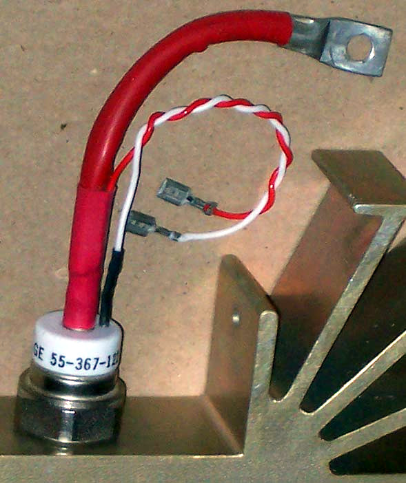
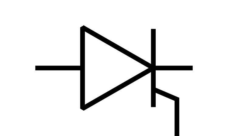
The Electronics Tutorial for Thyristor

William Shockley devised a thyristor, commonly known as an SCR (silicon-controlled rectifier). The United States' General Electric Company created the first thyristor product in 1957, and it went on sale in 1958. The thyristor is a four-layer, PNPN semiconductor device with three poles: anode, cathode, and gate. To operate, forward voltage must be applied, and the gate must have a trigger current. It is a high-power switching semiconductor device, denoted by the text symbols "V" and "VT" in the circuit (under the previous standard, it was denoted by the letters "SCR"). The thyristor exhibits the properties of a silicon rectifier device, is capable of operating at high voltages and currents, and has a controllable operating mechanism. It can be utilized in the circuit for frequency conversion, inverters, non-contact electronic switches, controlled rectification, and AC voltage management.

Types of Thyristor
Easybom will provide a brief overview of the many types of thyristors in the section that follows.
(1) Switching on, switching off, and controlling
Assorted thyristors, bidirectional thyristors, reverse conducting thyristors, gate turn-off thyristors (GTO), BTG thyristors, temperature-controlled thyristors, and light-controlled thyristors are some of the subtypes.
(2) Polarity and the pin
Depending on their pins and polarity, they can be classified as diode thyristors, triode thyristors, or quadrupole thyristors.
(3) Present capability
High-power thyristors, medium-power thyristors, and low-power thyristors are the three categories into which they can be separated. Medium and low-power thyristors are typically packaged in plastic or ceramic shells, while high-power thyristors are typically packaged in metal shells.
(5) Offset speed
High-frequency (rapid) thyristors and regular thyristors are two categories of thyristors.
How do thyristors function?
The main circuit of the thyristor is formed by connecting its anode (A) and cathode (K) with the power source and the load during operation.
A semi-controlled power electrical device called a thyristor or SCR operates under the following conditions:
- No matter what voltage the gate is exposed to, the thyristor is in the reverse blocking condition when the reverse anode voltage is applied.
- The thyristor will only conduct when the gate is exposed to a forward voltage when the thyristor is subjected to a forward anode voltage. The thyristor is currently in the forward conduction state, which is the controllable property of a thyristor.
- The thyristor remains on once it is switched on, regardless of the gate voltage, so long as there is a certain forward anode voltage; in other words, once the thyristor is turned on, the gate has no bearing. Only the gate serves as a trigger.
- After the thyristor is turned on, it is turned off when the voltage (or current) of the main circuit falls to nearly zero.


