

In this tutorial, I will discuss how to use the PIC16F84A microcontroller timer module for a variety of applications including turning a LED on and off without the use of a software delay subroutine.
Introduction
The PIC16F84A has one 8-bit free-running timer named TMR0. The term "free-running" means it continually runs in the background and has no start or stop control. You can read or write values from/to this timer. Since it's an 8-bit timer, the TMR0 can count from 0 to 255 (28 = 256).
Other microcontrollers have multiple timers with higher bit numbers: the PIC16F877A has two 8-bit and one 16-bit timer while the PIC18F4550 has three 16-bit and one 8-bit timer. Each count elapses after two instruction cycles by default. Recall that the instruction cycle speed is calculated (for a 4 MHz oscillator) using
You can extend the time it takes for each count using prescalers. When the timer reaches 255, the timer overflows and will go back to 0. An interrupt is associated with timer overflow.
Configuring the PIC Timer
All settings for the TMR0 is configured using the OPTION register. The PIC16F84A datasheet describes this register as follows:
The OPTION register is a readable and writable register which contains various control bits to configure the TMR0/WDT prescaler, the external INT interrupt, TMR0, and the weak pull-ups on PORTB.
Here are the bits for this register:
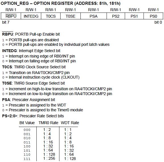
Look at bit 5 of the OPTION register named TOCS (TMR0 Clock Source Select). To use the timer, this bit should be cleared. If this is set, the TMR0 module is used for counting (discussed in a separate tutorial).
Prescaler
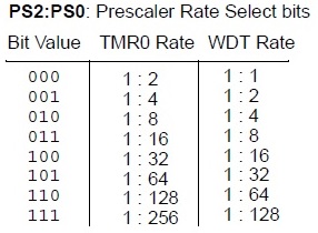
The prescaler will determine how many source edges will increment the TMR0 register value by 1. In short, the prescaler allows us to extend the time before the timer overflows. There are eight prescale settings which are chosen via the PS <2:0> bits of the OPTION register:
Bit 3 is the prescale assignment bit. Clearing it will assign the prescale to TMR0. Setting it would assign the prescale to the watchdog timer (which is another timer with a different use). Note that any write instructions to TMR0 (clrf, bsf, movwf, etc) will clear the prescale value.
Example: If the prescaler is set to the TMR0 and PS <3:0> is binary 2 (0102), then it would take 8 counts before the timer increments by one and so overflows after 2.04 milliseconds (assuming a 4 MHz crystal is used) because
Setting up the PIC Timer via ASM
Here is a short code snippet that configures the timer using the maximum prescale.
bsf STATUS, RP0 ;switch to Bank 1; OPTION register is at Bank 1
movlw 27h ;binary 00100111 - maximum prescale, assigned to TMR0
movwf OPTION_REG ;this is the name of the register on the .INC of P16F84A
bcf STATUS, RP0 ;switch to Bank 0
Turning an LED On/Off using PIC Timer
list p=16f84a
include <P16F84A.INC>

    org 0x00
    	goto start

start:
    bsf STATUS, RP0 	;switch to Bank 1
    bsf STATUS, RP0 		;switch to Bank 1; OPTION register is at Bank 1
    movlw 0x00
    movwf TRISB 			;PORTB all output
    movlw 07h 				;binary 00000111 - maximum prescale, assigned to TMR0
    movwf OPTION_REG 		;this is the name of the register on the .INC of P16F84A
    bcf STATUS, RP0 		;switch to Bank 0
    clrf TMR0 				;initialize the timer to zero
;---------------main routine
main:
    movf TMR0,0				 ;move contents of TMR0 to W
    andlw 0x01 				;mask so that only bit 0 of W is moved
    movwf PORTB 			;to PORTB
    goto main
end

What this code does is simply toggle the state of PORTB.0 synchronously with bit 0 of the TMR0 register. The toggling is a bit fast since the least significant bit changes state the fastest (around 254 microseconds for a 4 MHz crystal) for every count.
To make it slower, you can use the next bit (bit 1) by changing
andlw 0x01
to
andlw 0x02
Of course, PORTB.1 will now be blinking instead of PORTB.0. The slowest blink can be achieved if andlw 0x80 (masking the most significant bit) is used.
A One Second Delay
So how can we achieve a delay of one second? If you do the math, the timer overflows (max prescale, 4 MHz crystal) after 65.536 milliseconds. That's around 1/15 of a full second. Knowing this, we can wait for the timer to overflow 15 times before toggling the state of a pin. This is achieved by the code below:
list p=16f84a
include <P16F84A.INC>

    cblock 0x0c
    	COUNT
    endc

    org 0x00
    	goto start

start:
    bsf STATUS, RP0 		;switch to Bank 1
    movlw 0x10
    movwf TRISA 			;PORTA all output
    movlw 0x00
    movwf TRISB 			;PORTB all output
    movlw 07h 				;00000111
    movwf OPTION_REG 		;Counter mode, falling edge, prescaler set to maximum
    bcf STATUS, RP0 		;switch to Bank 0
    movlw 0x0F
    movwf COUNT

;---------------main routine
main:
bcf PORTB,0
movf TMR0,0
sublw .255
btfss STATUS, Z
goto main 					; keep looping until timer reaches 255
decfsz COUNT,1 				;if set, decrement COUNT
goto main 					;if count is not yet zero, repeat the loop
main2 bsf PORTB,0 			;if count reaches zero, set PORTB.0
movf TMR0,0 				;repeat process to delay turn off
sublw .255
btfss STATUS, Z
goto main2
decfsz COUNT,1
goto main2
goto main
end
What I did here is continually subtract 255 from TMR0. If TMR0 reaches 255, the result of the sublw .255 instruction would be zero, setting the Z bit of the STATUS register. When this happens, the COUNT variable which is initialized to 15, will be decreased by 1. PORTB.0 will be set when the COUNT variable reaches zero. The process is then repeated to delay the clearing of PORTB.0.
Although the above code works, I still suggest you use the timer overflow interrupt to delay things which uses less program space.
Next>> Asynchronous Serial (USART) Communication with PIC16F877A


