How to Use Lookup Tables in PIC Assembly

Programming a microcontroller in assembly languages takes time and to reduce that time, embedded systems engineers often have tricks up their sleeves. One of those tricks is the use of lookup tables. In this post, I will share how I use lookup tables in assembly language for the PIC16F84A microcontroller.
The RETLW Opcode
Lookup tables are possible in assembly primarily because of the RETLW opcode. This instruction means “return with a literal in w” and is used like this:
RETLW 0x04
Here, 0x04 is the literal value placed inside the W register before returning. Since the opcode returns to something, it is usually inside a subroutine.
Take note that RETLW reads the stack for the address to which to return. So a GOTO followed by RETLW will result in a stack underflow error.
Lookup Table Example
The most common lookup table is the one for seven segment displays. Frugal engineers don’t want to use decoders in using seven segment displays and so connect them directly to PIC pins. A lookup table is used to convert the numbers to their equivalent for seven segment displays.
Below is an example table:
table addwf PC
      retlw b’00111111’
      retlw b’00000110’
      retlw b’01011011’
      retlw b’01001111’
      retlw b’01100110’
      retlw b’01101101’
      retlw b’01111100’
      retlw b’00000111’
      retlw b’01111111’
      retlw b’01100111’
The binaries in this code are the seven-segment equivalent for digits zero to nine, assuming a common cathode displays and LSB at segment ‘a’.
Now if I want to display the digit seven (connected to PORTB), for example, I would do it like this:
movlw 0x07
call table
movwf PORTB
What this does is move a literal value 7 to W then call the lookup table. On the table, the value 7 adds to the current value of the program counter which is the first line of the table. The program then jumps 7 lines towards
retlw b’00000111’
The program now returns to the caller with W equal to the seven segment equivalent for the digit 7.
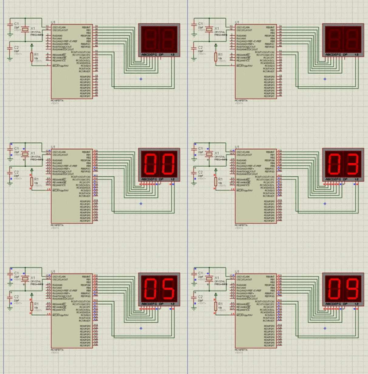
Example Project: Decade Counter
Let’s say we use two seven segment displays to count from zero to ninety-nine. One way to implement this is to assign variables to the ones and tens digits. As the ones digit go past 9, the tens digit increments by one. Using lookup tables make this project easier.
#include <P16F877A.inc>

__CONFIG _FOSC_XT & _WDTE_OFF & _PWRTE_OFF & _BOREN_OFF & _LVP_OFF & _CPD_OFF & _WRT_OFF & _CP_OFF

RES_VECT  CODE    0x0000         ; processor reset vector
    GOTO START                   ; go to beginning of program

INT_VECT CODE      0x0004        ; interrupt vector
    GOTO ISR                     ; go to interrupt service routine

MAIN_PROG CODE                      ; let linker place main program

CBLOCK 0x20
    micros
    ones
    tens
    count
ENDC

START
    bsf STATUS,RP0
    movlw 0x00
    movwf TRISB
    movlw 0x00
    movwf TRISC
    movlw 0x07
    movwf OPTION_REG
    bcf STATUS,RP0
    bsf INTCON,GIE
    bsf INTCON,TMR0IE
    clrf ones
    clrf tens
    clrf micros

MAIN
    movlw 0x02
    movwf PORTC
    movf ones, W
    call TABLE
    movwf PORTB
    call DELAY
    movlw 0x01
    movwf PORTC
    movf tens, W
    call TABLE
    movwf PORTB
    call DELAY
    goto MAIN

ISR
    bcf INTCON,GIE
    bcf INTCON,TMR0IE
    incf micros,1
    movf micros,0
    sublw 0x0F
    btfsc STATUS,Z
    goto inc_ones
    goto ret
inc_ones
    clrf micros
    incf ones, 1
    movf ones, 0
    sublw 0x0A
    btfsc STATUS,Z
    goto inc_tens
    goto ret
inc_tens
    clrf ones
    incf tens, 1
    movf tens, 0
    sublw 0x0A
    btfsc STATUS,Z
    clrf tens
    goto ret
ret bcf INTCON,TMR0IF
    bsf INTCON,GIE
    bsf INTCON,TMR0IE
    retfie

DELAY
    LOOP DECFSZ count,F
    GOTO LOOP
    RETURN

TABLE   addwf PCL
        retlw b'00111111'    ;digit 0
        retlw b'00000110'    ;digit 1
        retlw b'01011011'    ;digit 2
        retlw b'01001111'    ;digit 3
        retlw b'01100110'    ;digit 4
        retlw b'01101101'    ;digit 5
        retlw b'01111101'    ;digit 6
        retlw b'00000111'    ;digit 7
        retlw b'01111111'    ;digit 8
        retlw b'01101111'    ;digit 9

    END


