
We'll start with the PIC16F84A - a.k.a the beginner's microcontroller. This MCU from Microchip has been around since 1998 and is the successor to the very first serially programmable PIC, the PIC16C84. The PIC16F84A is often the starting point for learning PIC microcontrollers because it only has 35 assembly language instructions and it only costs less than $5 a piece. Creating a serial programmer for this microcontroller also won't take a lot of time.
The PIC16F84A
Here are the specifications of the PIC16F84A:
- Bus width - 8 bits
- Pin Count - 18 (PDIP, SOIC) / 20 (SSOP)
- Program Memory - 1750 bytes
- CPU Speed - 5 million instructions per second
- RAM Size - 68 bytes
- EEPROM Size - 64 bytes
The PIC16F84A is an 8-bit device which means almost all of its registers are 8-bits wide.
Program memory size tells you how much code can you burn inside the microcontroller. 1750 bytes of program memory is enough for simple applications which is where the PIC16F84A is common.
Five million instructions per second (MIPS) seems large until you compare it to modern CPUs. The Intel Core i7 5960x for example is rated 238, 310 MIPS.
RAM size is roughly the amount of registers you can use freely, like variables in high-level language programming (C++, Java, etc.).
EEPROM size tells you the amount of data you can store in the microcontroller which it will retain even if the power is turned off. For example, if you want the PIC16F84A to store a password, it can store up to 64 (ASCII) characters.
The disadvantage of the PIC16F84A is its lack of a number of essential microcontroller peripherals like analog-to-digital conversion and serial communications. The pin count can also be a limiting factor to some.
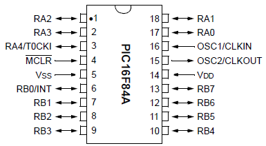
Here's the pin diagram for the PDIP/SOIC package:
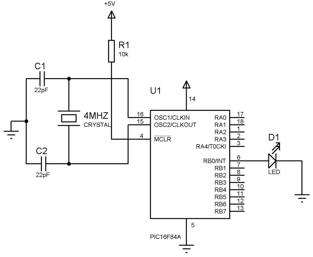
For this microcontroller to operate, you need a crystal oscillator connected to pin #16 and pin #15 and 22 pf capacitors from these pins to ground (see schematic below). If you can't find a crystal oscillator, there are other options. A 10 kΩ "pull-up" resistor connects to pin #4; doing this will prevent the PIC from accidentally resetting which happens if pin #4 is (briefly) grounded.
Simple LED Blink Program
At this point, we will try to build a very simple program for the PIC16F84A. We will blink an LED connected to pin #6 (RBO/INT) using assembly language. For the code explanation, read it here.
If you can't purchase a PIC16F84A and other physical components, I suggest you use simulation software such as Proteus ISIS.
First, we'll wire this schematic diagram:
Our First Assembly Code

; TODO INSERT CONFIG CODE HERE USING CONFIG BITS GENERATOR
#INCLUDE <P16F84A.INC>

RES_VECT  CODE    0x0000            ; processor reset vector
    GOTO    START                   ; go to beginning of program

; TODO ADD INTERRUPTS HERE IF USED

CBLOCK 0x0C
    COUNT1
    COUNT2
ENDC


MAIN_PROG CODE                      ; let linker place main program

 START
    BSF STATUS, RP0
    MOVLW 0xFE
    MOVWF TRISB
    BCF STATUS, RP0

 MAIN
    BSF PORTB,0
    CALL DELAY
    BCF PORTB,0
    CALL DELAY
    GOTO MAIN

 DELAY
    LOOP1 DECFSZ COUNT1, 1
    GOTO LOOP1
    DECFSZ COUNT2,1
    GOTO LOOP1
    RETURN

    END
Compile this program, load it to your PIC in ISIS simulation (or load it directly to your PIC using Pickit3), and see the results!


