In my previous post, I showed you how to set up an 8051 microcontroller for programming using C. This tutorial will be about how to interface with seven-segment displays.
Review on Seven Segment Displays
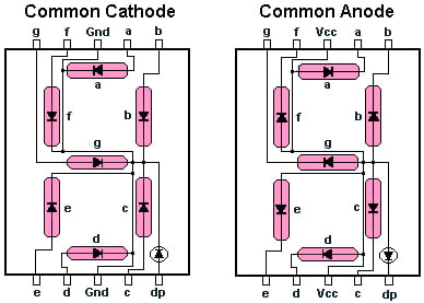
A seven-segment display consists of LEDs in parallel. This way, each LED or "segment" can be turned on or off. Recall that an LED emits light when the anode voltage is more positive than the cathode voltage.
In a common cathode seven-segment display, each anode of the LEDs is accessible while all LED cathodes connect into one pin. The anode pins are given labels A to G. The opposite is true for a common anode display. Here, we will limit ourselves to common cathode displays.
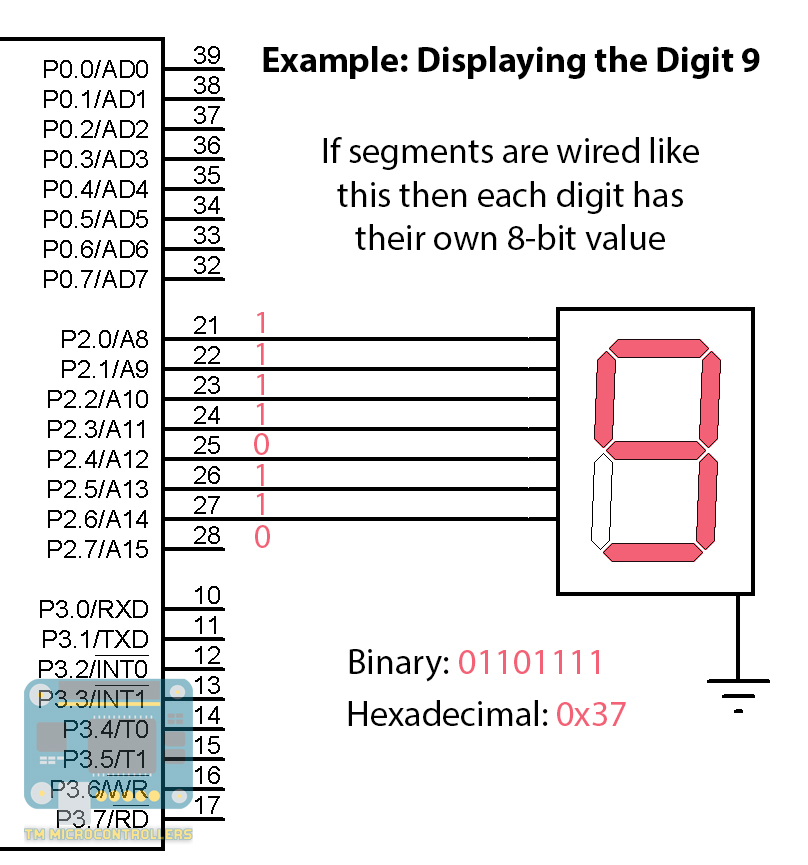
To display a number in a seven-segment display, the correct LEDs should light up. Hence if each anode connects to a pin in the 8051 microcontroller, digits 0 to 9 corresponds to an 8-bit value of a port.
Here’s a table showing all 8-bit values for digits 0 to 9, assuming segment A wires to the port’s LSB.
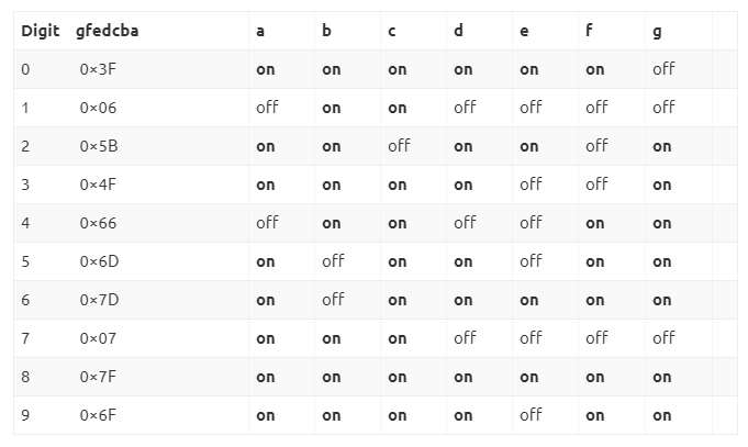
Based on the table above, we create a function that accepts a digit as a parameter and returns the corresponding 8-bit value.
int toSevenSeg(int num)
{
  switch(num){
    case 0:
        return 0x3F;
        break;
    case 1:
        return 0x06;
        break;
    case 2:
        return 0x5B;
        break;
    case 3:
        return 0x4F;
        break;
    case 4:
        return 0x66;
        break;
    case 5:
        return 0x6D;
        break;
    case 6:
        return 0x7C;
        break;
    case 7:
        return 0x07;
        break;
    case 8:
        return 0x7F;
        break;
   case 9:
        return 0x67;
        break;
   default:
        return 0x64; //return dash if invalid
   }
}
The function returns an integer and so we can pass it directly to any port.
P2 = toSevenSeg(x);
8051 Code for Interfacing with One Display
The example code below shows the digits 0 to 9 in succession with a second interval in between.
#include<reg51.h>           // special function register declarations
                            // for the intended 8051 derivative

// delay subroutine
void DELAY_ms(unsigned int ms_Count)
{
    unsigned int i,j;
    for(i=0;i<ms_Count;i++)
    {
        for(j=0;j<100;j++);
    }
}

// seven-segment converter routine
int toSevenSeg(int num)
{
  switch(num){
    case 0:
        return 0x3F;
        break;
    case 1:
        return 0x06;
        break;
    case 2:
        return 0x5B;
        break;
    case 3:
        return 0x4F;
        break;
    case 4:
        return 0x66;
        break;
    case 5:
        return 0x6D;
        break;
    case 6:
        return 0x7C;
        break;
    case 7:
        return 0x07;
        break;
    case 8:
        return 0x7F;
        break;
   case 9:
        return 0x67;
        break;
   default:
        return 0x64; //return dash if invalid
   }
}
// main routine
int main()
{
    unsigned int x;
    while(1)
    {
        //display digits 0 to 9 with 1 second interval
        for(x=0;x<10;x++)
        {
	    P2 = toSevenSeg(x);
	    DELAY_ms(1000);
	}
    }
    return (0);
}
8051 Code for Interfacing with Multiple Displays
We can use multiple seven-segment displays by connecting the common cathode pin to a microcontroller pin. This way, we can multiplex the displays using the common cathode pin as the switch. The switching should be fast enough to trick our eyes that all displays are on simultaneously instead of alternating. This is also called persistence of vision.
Here is a code that uses two seven-segment displays to count from 00 to 99.
#include<reg51.h>           // special function register declarations
                            // for the intended 8051 derivative
sbit SW1 = P3^0;
sbit SW2 = P3^1;

// speed between display switch
#define SWITCH_SPEED 40
// speed between counts
#define COUNT_SPEED 15

// delay subroutine
void DELAY_ms(unsigned int ms_Count)
{
    unsigned int i,j;
    for(i=0;i<ms_Count;i++)
    {
        for(j=0;j<100;j++);
    }
}

// seven-segment converter routine
int toSevenSeg(int num)
{
  switch(num){
    case 0:
        return 0x3F;
        break;
    case 1:
        return 0x06;
        break;
    case 2:
        return 0x5B;
        break;
    case 3:
        return 0x4F;
        break;
    case 4:
        return 0x66;
        break;
    case 5:
        return 0x6D;
        break;
    case 6:
        return 0x7C;
        break;
    case 7:
        return 0x07;
        break;
    case 8:
        return 0x7F;
        break;
   case 9:
        return 0x67;
        break;
   default:
        return 0x64;  //return dash if invalid
   }
}
// main routine
int main()
{
    unsigned int ones, tens, counter;
    ones = 0;
    tens = 0;
    counter = 0;
    while(1)
    {
	SW1 = 1;
	SW2 = 0;
	P2 = toSevenSeg(ones);
	DELAY_ms(SWITCH_SPEED);
	SW1 = 0;
	SW2 = 1;
	P2 = toSevenSeg(tens);
	DELAY_ms(SWITCH_SPEED);
	counter++;
	if(counter > COUNT_SPEED)
        {
	    ones++;
	    counter = 0;
	}
	if(ones > 9)
        {
	    tens++;
	    ones = 0;
	}
	if(tens > 9) tens = 0;
   }
   return (0);
}
The SWITCH_SPEED and COUNT_SPEED for the code above should be chosen after testing the actual physical circuit. SWITCH_SPEED is the time interval between turning on one display and then turning on the other. COUNT_SPEED is the speed of the counting.
For questions regarding this tutorial, please drop a comment below!
 with Seven-segment Displays")