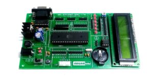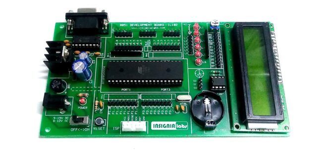
We continue with our series on the 8051 with a tutorial on serial transmission. Data communications via the serial port is an easy way for a microcontroller to ‘talk’ with the outside world. Examples of devices that have serial interfaces are sensors, LCDs, EEPROM, SD cards, and RTCs.
Here, I will be skipping the basics of serial communications and proceed directly on how to use it with 8051 and the C language. In particular, we will be focusing on the RS-232 protocol.
8051 Registers for Hardware UART
8051 contains a number of registers that give the microcontroller a certain feature. This is also true with other MCUs like PIC, STM32, and AVR (Arduino). To be able to use the 8051’s serial port, we need to use a number of registers.
Serial Port Control
The first register is the SCON or Serial Port Control Register. It is an 8-bit register with each bit having their own use:
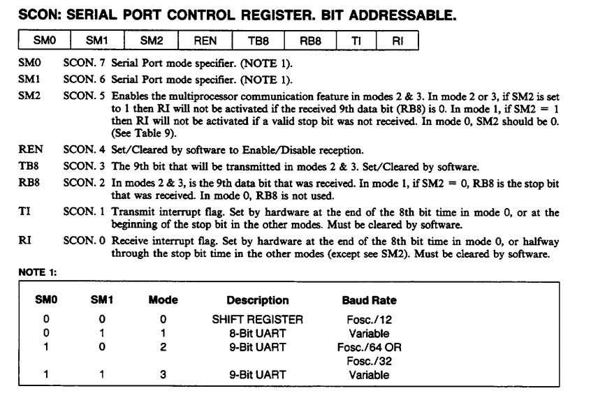
The important bits here are SM0 and SM1 as they set the serial mode of 8051. There are four modes as shown above (NOTE 1).
For this example, we will be using Mode 1 and leave the rest of the bits as clear. However, take special note of bit T1 as we will be also using that later.
Timer/Counter Mode Control
Serial communication requires that both transmitter and receiver are in sync. For the RS232 protocol, the only way to sync is that both TX and RX have the same baud rate. The 8051 has its own baud rate generator and requires the use of one of the two timer modules.
And so, the next register that we need is the TMOD or Timer/Counter Mode Control register. Here are the bits of this register:
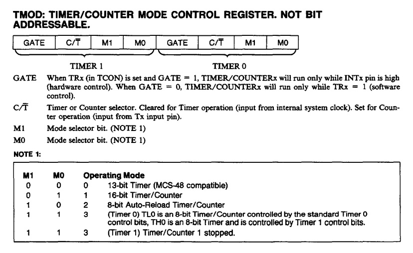
The register is divided into two parts, depending on which timer we will use. For this tutorial, we will be using Timer 1. Hence, our concern is only the high byte of TMOD. We are selecting Mode 2; we set bit M1, and clear bit M0. More on this mode later below.
Power Control Register
Next, we have the PCON register. We only have one bit to use here and that’s the SMOD bit:
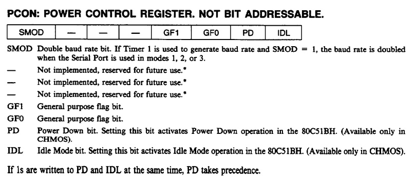
When SMOD is 1, the baud rate is doubled. Otherwise, the baud rate stays the same.
Timer/Counter Control Register
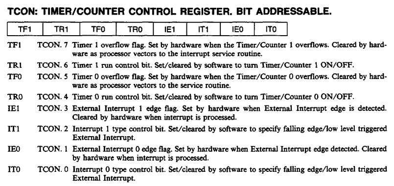
Since the serial port relies on Timer 1, we need to enable it by setting the TR1 bit of the TCON register:
Other Registers
Finally, we have registers TH0, TL0, TH1, and TL1. These registers represent the high byte and low byte of 16-bit timers 0 and 1. Recall that we choose Timer 1 via TMOD register. Moreover, we choose Mode 2: 8-bit auto-reload. This mode allows us to modify only TH1 since TL1 is loaded from TH1 at the beginning of each cycle.
Baud Rate Calculation
The 8051 baud rate formula is:
![]()
Where FOSC is the 8051's crystal oscillator and TH1 the high byte value of Timer 1. What we want is to specify the value of TH1 for our target baud rate. So, reversing the formula:
![]()
For example, to achieve a baud rate of 2400 with a 12 MHz crystal, your TH1 value should be (SMOD=0):
![]()
Remember that TH1 is an 8-bit register and holds integers only.
The actual baud rate is then:
![]()
It’s not exactly 2400 but with just 0.16% of deviation, it works.
C Code for 8051 Serial Interfacing
Here’s a C code that prints out Hello World! through the serial port at 2400 baud:
#include <reg51.h>
#include <stdio.h>

#define FOSC 12000000

void serial_init(unsigned long int baud)
{
  unsigned long int divisor = 256 - (FOSC/(384*baud));
  SCON = 0x40;
  TMOD = 0x20;                           /* TMOD: timer 1, mode 2, 8-bit reload      */
  TH1 = divisor;			 /* load divisor to Timer 1 High Byte (TH1)  */
  TR1   = 1;                             /* TR1:  timer 1 run                        */
  TI    = 1;                             /* TI:   set TI to send first char of UART  */
}

void main (void)
{
  serial_init(2400);
  while(1)
  {
    printf("Hello world!\n");
  }
}
Here we define a function that initializes the hardware UART:
void serial_init(unsigned long int baud)
{
  unsigned long int divisor = 256 - (FOSC/(384*baud));
  SCON = 0x40;
  TMOD = 0x20;       /* TMOD: timer 1, mode 2, 8-bit reload */
  TH1 = divisor;     /* load divisor to Timer 1 High Byte (TH1) */
  TR1 = 1;           /* TR1: timer 1 run */
  TI = 1;            /* TI: set TI to send first char of UART */
}
This function is called in main() where its parameter is the desired baud rate:
void main (void)
{
   serial_init(2400);
   while(1)
   {
       printf("Hello world!\n");
   }
}
Also notice that we use the function printf() which belongs to the stdio library, hence the added definition at the top of the code. Remember bit TI in SCON? The printf() function uses that bit to determine when to start or stop sending characters on the serial port. If TI is not set, the print() function will not work.
While we were able to make it work at 2400 baud, other baud rates may not work.
For example, choosing 9600 baud will generate the following value for TH1:
![]()
Calculating the actual baud rate using this TH1 value:
![]()
That’s an 8.5% difference from the desired baud rate of 9600! Your options for this one would be to try changing the crystal oscillator, use a different timer and/or apply the SMOD bit.
You could try Keil’s baud rate generator to determine the best oscillator value for your target baud rate. For example, using 11.0952 MHz at mode 2 and SMOD = 0 generates a rate of 9,631.25 which is at 0.33% deviation for the standard 9600 baud.
That's it for this tutorial! See you in the next part of this 8051 series.


 Tutorial")