
I got plenty of questions regarding microcontroller power outputs and requirements especially for popular ones like PIC or the Arduino. So I decided to answer all of them in this post. Technically, Raspberry Pi and BeagleBone Black are not microcontrollers (I like to call them microcomputers) but I decided to include them here. Do you want to know if you really need a resistor for a LED connected to an Arduino port? Or is your power supply enough to turn on a Raspberry Pi? Read on.
PIC Microcontroller Power Requirements
The answer to power questions about the PIC can be found on the device’s datasheet. The recommended and absolute maximum ratings can be found on the Electrical Characteristics of every datasheet. For example, this is what’s found on the PIC16F87XA family’s datasheet:
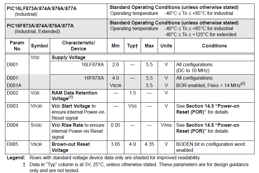
The "Typ" or typical values is blank but if you look at the footnote, it says that the typical value is 5V at 25 °C. Then you have the maximum supply voltage as 5.5 V and a minimum of 4 V. The 2 V minimum is for the 16LF87XA model which is specially made as a low-power device.
Now look at this part of the datasheet:
These are the absolute maximum ratings for the PIC16F87XA family. If you look at the third line, it says that the voltage on any pin except for VDD, MCLR and RA4 should be -0.3 V to VDD+0.3V with respect to VSS. Normally VSS is connected to ground or 0 V. This means you have a 0.3 V allowance on the pins and beyond that your device might be permanently damaged. So let’s say your VDD is 5 V, then the voltage on the pin should not exceed 5.3 V. On the other end, the pin is allowed to have a negative voltage with respect to VSS but it should not exceed 0.3 V.
The voltage on the MCLR pin can absorb higher voltages for the device to enter programming mode. The voltage on RA4 is also higher to facilitate reception of pulses.
We also see that VDD with respect to VSS is 7.5 V max. This means the device can withstand a supply of 7.5 V but for normal operations, 5.5 V as a maximum is recommended.
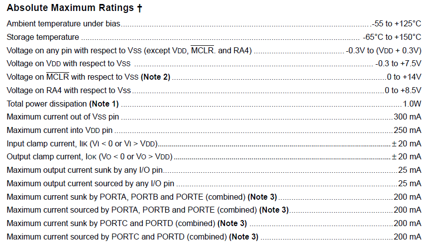
Now let’s look at the current ratings. There are interesting areas from the datasheet:

It says that the maximum current that any I/O pin can absorb is 25 mA. Beyond that, the pin and maybe the device itself is damaged. Similarly, the maximum output current by any pin is 25 mA.
We can also see that each PORT can source and sink 200 mA of current. The math checks out for PORTB, PORTC, and PORTD which are 8-bit pins:
PORTA and PORTE have less than 8 pins but sources and sinks the same 200 mA of current.
Now let’s answer the question: do I really need a resistor for a LED connected to a PIC’s pin?
I searched a LED in Digikey to use as an example and found this one from Lite-On. This is what is found on its datasheet:

We can see that its maximum continuous forward current is 15 mA while its peak forward current is 60 mA. What this means is that it can withstand up to 60 mA in short bursts (0.1 ms) but can only withstand 15 mA of constant level current.
In another part of the datasheet, I found this:

This tells us the forward voltage of the LED (2.1 V) at a forward current of 20 mA. This gives us a resistance of 105 ohms. This value is correct if you look at the forward voltage vs forward current graph of the LED:

Now that we have data, let’s try some calculation. Without a resistor, the current through the LED would be:
That is well beyond the maximum continuous forward current for this LED. Wait, the PIC can only source a maximum of 25 mA right?
So what this means is not only are you in danger of damaging the LED, you are also drawing current from the pin of the PIC beyond its limit. That’s double damage.
Also, if you calculate the power dissipation for this example:
That is twice the maximum power rating of 40 mW!
In short, for this specific LED, it is not safe to connect directly to the PIC’s output pin without a resistor.
Ideally we would want only 10 mA of forward current for the LED. To calculate the needed resistor, you can use this formula:
For example, using (according to the graph for a forward current of 10 mA), the resistor value should be:
Arduino Power Requirements
For this discussion, I will be using the Arduino UNO as an example which is using AVR’s ATMega328p microcontroller. This could extend to all other Arduinos that uses the same microcontroller.
Here’s the maximum ratings for the ATMega328p:

It is interesting to note that this device has a slightly higher voltage tolerance compared to the PIC16F877X. We also see that each pin can source and sink (I assume as it is not explicitly stated that the value is source or sink) 40 mA. This means the ATMega328p can withstand the current drawn by the a resistor-less LED circuit as in our previous example. That doesn’t mean the LED is not in danger of being damaged though.
I also found this one interesting:

It says the the ATMega328p consumes a higher current at a higher frequency. The Arduino UNO board uses a 16 MHz oscillator which, unfortunately, is not part of the table.
I tried to find out how much the UNO board really is consuming but there seems to be no concrete document for it. The two highest power consumers would be the ATMega328p and ATMega16p. Again, both uses a 16 MHz oscillator and the current consumption for this oscillator value is not found on the datasheet.
As for sourcing power from the Arduino UNO, the 5 V and 3.3 V pins give different values and would depend on which power source the Arduino UNO is connected. If the board is connected to a computer’s USB port, then the 5 V pin can theoretically source 500 mA based on the maximum current from the port. If an external supply is used, the output current from the 5 V pin is limited by the 900 mA max current for the 5 V regulator (NCP1117). Similarly, the 3.3 V pin is limited by the 3.3 V regulator (LP985) which gives a maximum current of 150 mA.
Again, these figures are only for the Arduino UNO. I will be updating this to include other Arduino boards in the future.
Raspberry Pi Power Requirements
As of this writing, there are 8 Raspberry Pi models and each have different power requirements. The official FAQ gives these values:

The recommended voltage level for the supply should be within 4.75 V to 5.25 V. The Raspberry Pi B+, 2 and 3 includes a voltage monitor chip which triggers at 4.56 V to 4.7 V. This chip is wired to the red LED you see on the board. If that LED illuminates then your power supply is enough.
As for the current that the pins of the Raspberry Pi can source and sink, there is no official documentation. Even the RPi’s CPU datasheet doesn’t give electrical specifications for the pins. One of the engineers of the original board, Gert van Loo, claims that “all the electronics of the pads are designed for 16mA. That is a safe value under which you will not damage the device. … Other than that there is no guaranteed maximum safe current."
The 5V pin on the Raspberry Pi is directly connected to the external power source so that sets it limits. Determining the maximum power from the 3.3 V rail is more complicated which thankfully, the author of this article already covered. According to the article, the 3.3 V rail can supply 800 mA with an adequate external power supply.
BeagleBone Black Power Requirements
The only reference we have for the current source or sink of each GPIO of the BeagleBone Black is Sitara AM335x datasheet. Honestly, the datasheet was not that helpful and it took a lot of diligence for me to come up with the ratings.
Typically, all the pins can accommodate 6 mA of current except these ones which can only source 4 mA:
P9_19
P9_20
P9_24
P9_26
P9_41
P9_42
As for the USB power, the chip used is TPS2051 which complies with the USB standard of 500 mA. Meanwhile the DC connector can accept voltages from 4.75 to 5.25 V.
Adafruit made a good article on how the Beaglebone Black compares to the Arduino Yun, Raspberry Pi and Intel Galileo in terms of power consumption. The current draw from the 5V input for each board was recorded while each of them are connected to a network via their respective Ethernet port. Here are the results:
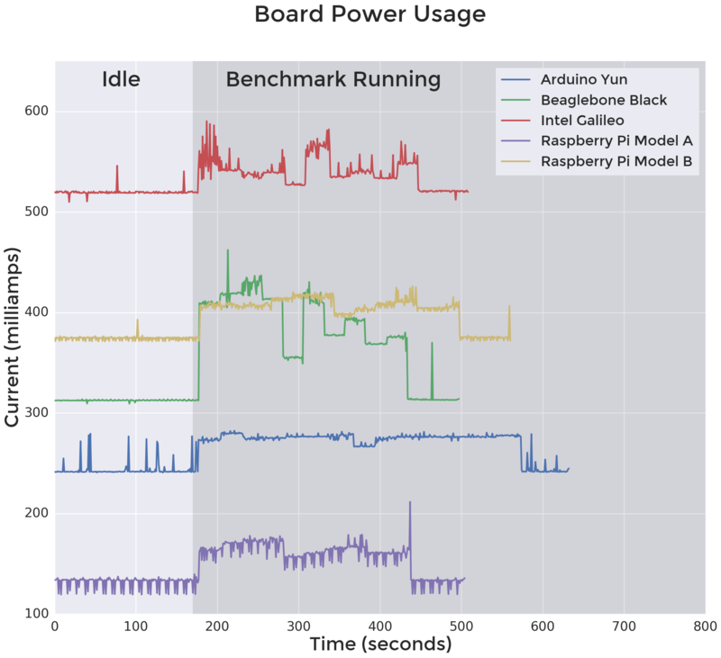
The time from 0 to 180 seconds is idle time. We can see that the Beaglebone Black lies in between the other boards in terms of power consumption. During active phase, the BBB consumes just about the same power as the Raspberry Pi Model B. Not surprisingly, Intel’s Galileo consumes the largest power.
Hopefully this post answered questions about power on the popular microcontroller and microcomputers. If you have further questions, kindly drop a comment below!


