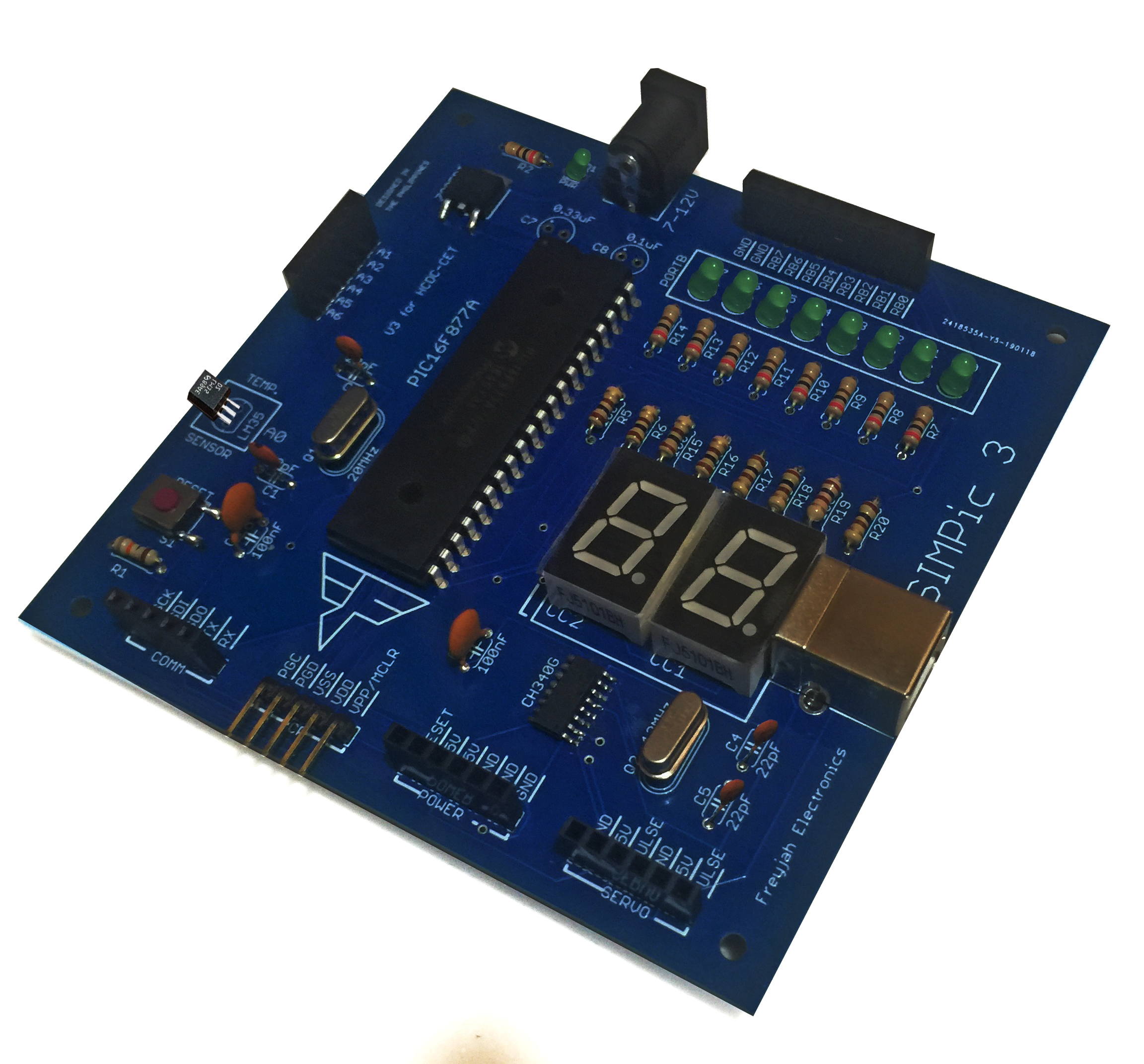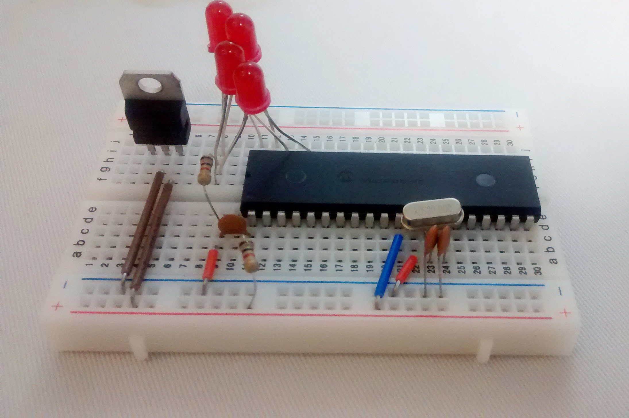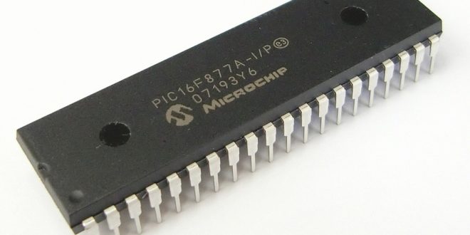
We have managed to blink an LED and use interrupts and timers with the PIC16F84A. Sadly, that’s almost all we can do with that microcontroller as it lacks features that most microcontrollers or Arduino have. From here on, we will now be using the PIC16F877A.
The PIC16F877A is a 40-pin (DIP) microcontroller which Microchip describes as powerful based on having a 200 nanosecond instruction speed. It’s old and Microchip itself is not recommending it for new designs but its features and price make it still a popular microcontroller.
PIC16F877A Specs
Here are a few of its specifications:
- Bus width - 8 bits
- Pin Count - 40 (PDIP, SOIC) / 44 (QFN, PLCC, TQFP)
- Program Memory - 14.3 kilobytes
- CPU Speed - 5 million instructions per second
- RAM Size - 368 bytes
- EEPROM Size - 256 bytes
Obviously, the PIC16F877A trumps the PIC16F84A based on the numbers above. But what separates this microcontroller are these features:
- 10-bit, up to 8-channel Analog-to-Digital
Converter (A/D) - Synchronous Serial Port (SSP) with SPI™
(Master mode) and I2C™ (Master/Slave) - Universal Synchronous Asynchronous Receiver
Transmitter (USART/SCI) with 9-bit address
detection
We will discuss each of these features as we continue with this tutorial.
LED Blink Code in Assembly
For now, we will create a simple assembly language program using the PIC16F877A.
The code is very similar to the one using PIC16F84A:
#INCLUDE <P16F877A.INC>

 __CONFIG _FOSC_XT & _WDTE_OFF & _PWRTE_OFF & _BOREN_OFF & _LVP_OFF & _CPD_OFF & _WRT_OFF & _CP_OFF

RES_VECT  CODE    0x0000            ; processor reset vector
    GOTO    START                   ; go to beginning of program

; TODO ADD INTERRUPTS HERE IF USED

    CBLOCK 0x0C
	COUNT1
	COUNT2
    ENDC

MAIN_PROG CODE                      ; let linker place main program

START
    BSF STATUS, RP0
    CLRF TRISB
    BSF TRISA,0
    BCF STATUS, RP0

MAIN
    BSF PORTA,0
    CALL DELAY
    BCF PORTA,0
    CALL DELAY
    GOTO MAIN

DELAY
LOOP1   DECFSZ COUNT1,1
	GOTO LOOP1
	DECFSZ COUNT2,1
	GOTO LOOP1
	RETURN

    END
The code above simply toggles the state of pin RB0. So when an LED is attached to this pin, it will blink. You can simulate this code in Proteus using the schematic diagram below:
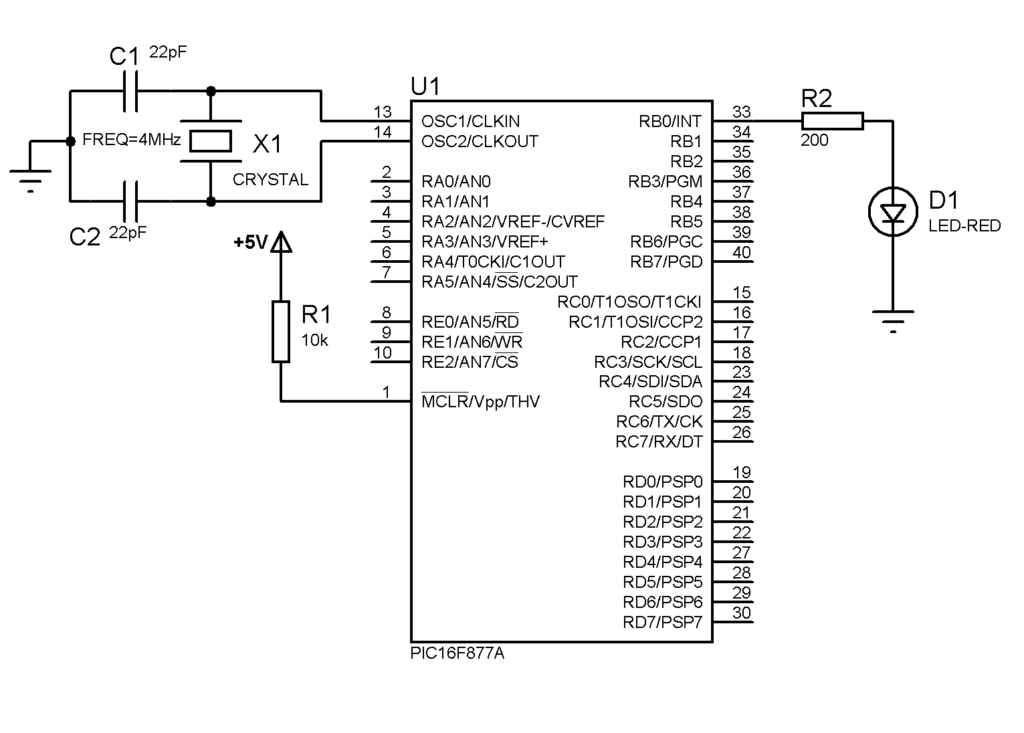
Of course, the advantage of using this microcontroller is you can attach a lot more LEDs!
Switch an LED in Assembly
For input using a switch, you can freely use any pin except those that have AN labels. These analog pins including all PORTA and PORTE pins are meant for analog-to-digital conversion and need a bit of additional code to make them digital.
To turn these analog pins to digital, we must write 0x07 or 0x06 to the ADCON1 register. Details about this are found in my analog-to-digital conversion tutorial.
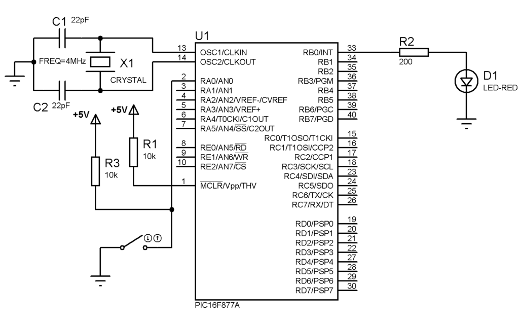
Here’s a code that uses a switch to RA0 to turn on/off a LED:
#INCLUDE <P16F877A.INC>

 __CONFIG _FOSC_XT & _WDTE_OFF & _PWRTE_OFF & _BOREN_OFF & _LVP_OFF & _CPD_OFF & _WRT_OFF & _CP_OFF

RES_VECT  CODE    0x0000            ; processor reset vector
    GOTO    START                   ; go to beginning of program

; TODO ADD INTERRUPTS HERE IF USED

    CBLOCK 0x0C
	COUNT1
	COUNT2
    ENDC

MAIN_PROG CODE                      ; let linker place main program

START
    BSF STATUS, RP0
    CLRF TRISB
    MOVLW 0x07
    MOVWF ADCON1
    MOVLW 0x01
    MOVWF TRISA
    BCF STATUS, RP0

MAIN
    BTFSC PORTA,0
    GOTO OFF
    GOTO ON
    GOTO MAIN

ON  BSF PORTB,0
    GOTO MAIN

OFF BCF PORTB,0
    GOTO MAIN

DELAY
LOOP1   DECFSZ COUNT1,1
	GOTO LOOP1
	DECFSZ COUNT2,1
	GOTO LOOP1
	RETURN

    END
Here’s the schematic diagram for the code above:
Those are the basic assembly language programs we can do with the PIC16F877A. Up next, we will look at the features that separate this microcontroller from the PIC16F84A, starting with serial communication.