
This project demonstrates how two Bluetooth modules connect with each other. I’ll be featuring DFRobot’s Input Shield V2 as the transmitter/controller and Seeed’s ShieldBot, which was seen on my Bluetooth RC Car project, will act as the receiver.
Setup
The Bluetooth modules I’ll be using are the old but still popular HC-05 modules. The first step is to make one module as master and another as slave. The module is slave by default so we only need to reconfigure one to be the master.
The HC-05 modules I own is the one without the KEY pin. In case you don’t know, the KEY pin, when driven high, gets the module into AT command mode.
My module contains a button for supposedly getting it to command mode by pressing and holding it before applying power to the module. It works but only during startup. To keep the module in command mode, pin 34 must be kept high. This is shown below:
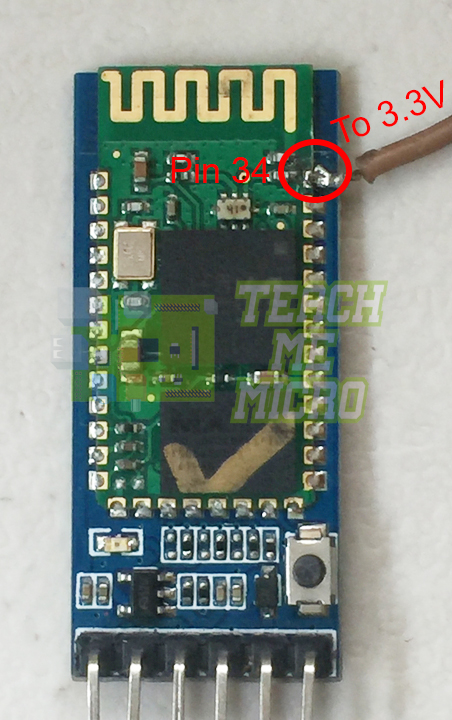
The brown wire shown must be connected to the 3.3V pin. If successful, the red LED will flash once every two seconds.
I used an FTDI USB to Serial converter to configure the Bluetooth module once it’s in command mode. Then I used Arduino’s serial monitor to send out commands. The default baud rate for command mode is 38400.
To check if the HC-05 is indeed in command mode, I sent:
AT
> OK
"OK" here is the module's reply.
Next, I reset the configurations to its default values:
AT+ORGL
> OK
Then, I set the module to master:
AT+ROLE=1
> OK
Next, reset the module:
AT+RESET
> OK
Then when its back, initialize:
AT+INIT
> OK
Now, I want the module to link with only one device: the slave HC-05 on my robot car. To forget all the previous connections, I sent:
AT+RMAAD
> OK
After this, I turned on the slave HC-05 because I needed to know its MAC address. Knowing the MAC address of available devices is simple. Just issue:
AT+INQ
> +INQ:98D3:31:FC20A9,1F00,7FFF
Here, it shows that my slave device has a MAC address of 98D3:31:FC20A9. The 1F00 is the device class while the 7FFF is the received signal strength indicator (RSSI).
To pair with the slave device:
AT+PAIR=98D3,31,FC20A9,20
> OK
The parameter for the AT+PAIR command is just the address of the slave address but is now separated by the comma instead of the colon and the timeout period (20 seconds in this example). After pairing, the LED on the master module will start flashing with about two seconds of pause.
Next, we bind the master and slave devices by using:
AT+BIND=98D3,31,FC20A9
> OK
Finally, we link the two devices through:
AT+LINK=98D3,31,FC20A9
> OK
If successful, both the master and slave device's LED will now blink twice followed by about two seconds of pause.
The good thing is even if I remove power from either master or slave, they will automatically connect with each other when both are turned on!
Wiring Up the Wireless Controller
Now that I’ve linked two Bluetooth modules together, it’s time to attach the master device to DFRobot’s Input shield. Here’s my setup:
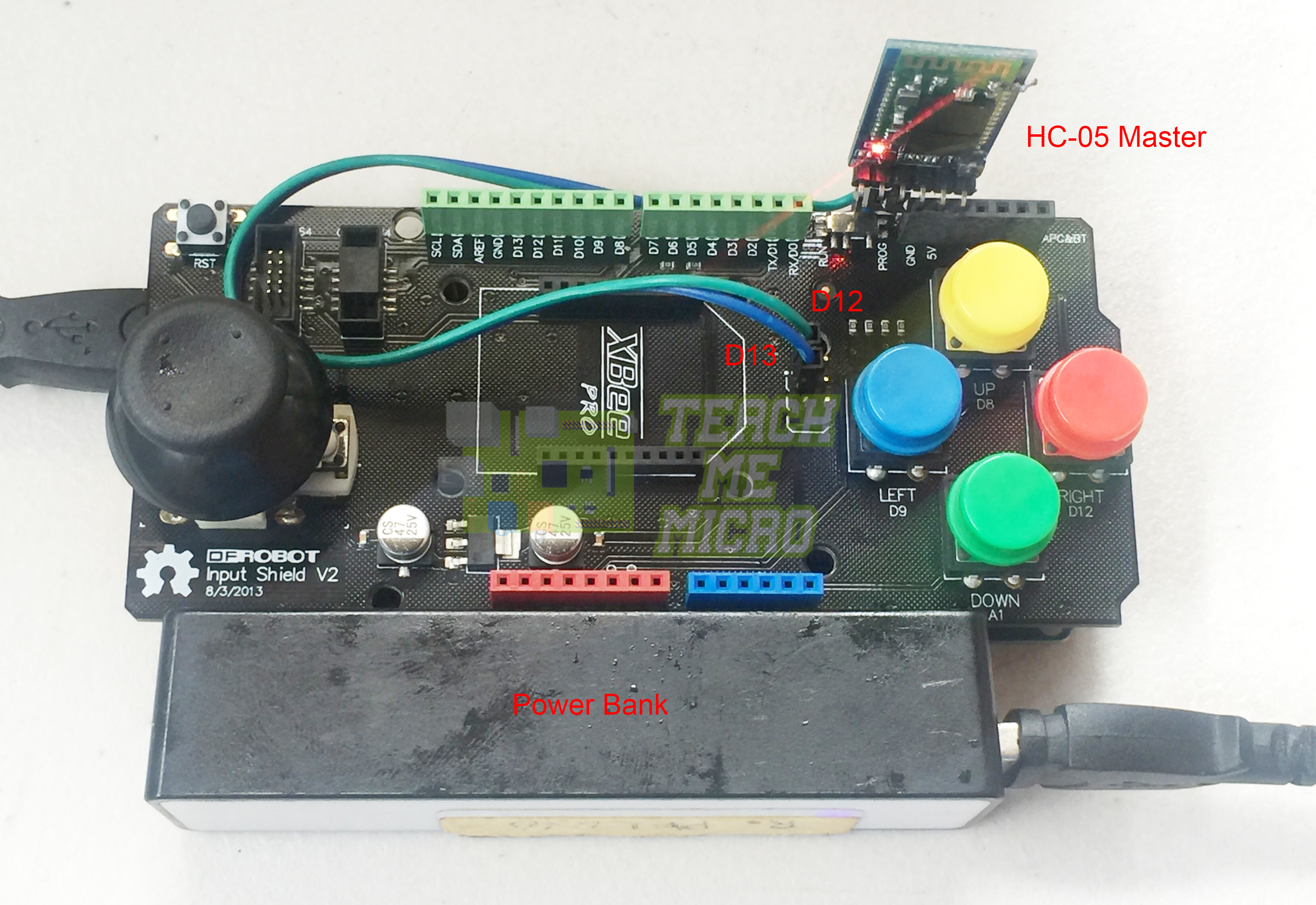
I used an Arduino Mega with the shield but a UNO could work too. The Shield has an eight-pin female header on the top right side. It would’ve been awesome if the HC-05 fits there but it doesn’t. Naturally, I had to improvise. I still used the header but only its 5V and GND pins. The TX and RX pins of the module are connected to D13 and D13 respectively, via the ICSP header. The power to the controller is provided by a small power bank.
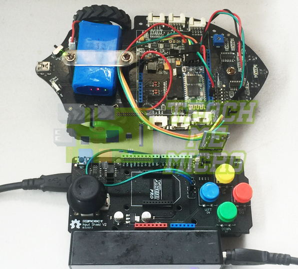
Here is the controller with the Shield-Bot:
Arduino Sketch
The shield bot setup is the same as that in my Bluetooth RC car project. You can view the Arduino sketch for the robot there. In that project, the robot moves when the Bluetooth module receives the following commands:
- "f" -> forward
- "b" -> backward
- "l" -> left
- "r" -> right
So all I need to do is make the controller send these characters wirelessly. I decided to use only the controller's joystick for the moment.
After testing, I found out that the joystick Y-axis is connected to A2, and the X-axis is connected to A3. When the joystick is all the way to the right, the A3 value is 0. Similarly, when the joystick is all the way up, A2 is zero. This means all the way left and down could be 1023 for A3 and A2.
Here is my sketch for the controller:
#include <SoftwareSerial.h>

SoftwareSerial Bluetooth(13, 12); // RX, TX

#define up_button  8
#define down_button A1
#define left_button 9
#define right_button  12

#define stick_button  A0
#define level_stick A3
#define vertical_stick  A2

void setup() {
  Bluetooth.begin(9600);
  Serial.begin(9600);
  Serial.println("Waiting for command...");
  Bluetooth.println("Waiting for command");

  pinMode (left_button, INPUT);
  pinMode (right_button, INPUT);
  pinMode (up_button, INPUT);
  pinMode (down_button, INPUT);

  pinMode (stick_button  , INPUT);
  pinMode (level_stick   , INPUT);
  pinMode (vertical_stick, INPUT);
}

void loop() {
  int left_state = digitalRead (left_button);
  int right_state = digitalRead (right_button);
  int up_state = digitalRead (up_button);
  int down_state = digitalRead (down_button);
  int stick_state = digitalRead (stick_button);
  int level_value = analogRead (level_stick);
  int vertical_value = analogRead (vertical_stick);
  if(level_value > 800){
    Bluetooth.println("l");
    Serial.println("l");
  }else if(level_value == 0){
    Bluetooth.println("r");
    Serial.println("r");
  }else if(vertical_value > 800){
    Bluetooth.println("b");
    Serial.println("b");
  }else if(vertical_value == 0){
    Bluetooth.println("f");
    Serial.println("f");
  }else{
    Bluetooth.println("s");
    Serial.println("s");
  }
  delay (500);
}
That’s it! Thanks for viewing this project. If you have any concerns, kindly drop a comment!


