The ESP32-S3 is one of Espressif's most capable microcontrollers, combining Wi-Fi, Bluetooth Low Energy, USB support, a large number of GPIO pins, and hardware intended for signal-processing and AI workloads. However, taking full advantage of the ESP32-S3 requires understanding which GPIO pins are available and which pins have special functions.
This guide provides a complete ESP32-S3 pinout reference, including the GPIO pins used for ADC, touch sensing, PWM, UART, SPI, I2C, USB, JTAG, and boot configuration. We will use the popular ESP32-S3-DevKitC-1 as our reference development board, although most of the GPIO information also applies to other ESP32-S3 boards. If you're new to the board, see our ESP32-S3 Getting Started Guide for Arduino IDE setup, board configuration, uploading your first sketch, and basic testing.
One important difference from the original ESP32 is that the ESP32-S3 has a much larger number of available GPIO pins. It also includes native USB support and as many as 14 capacitive-touch inputs.
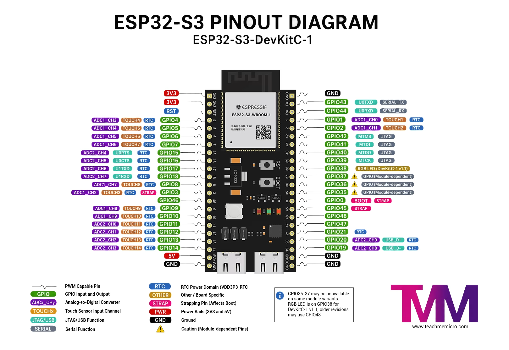
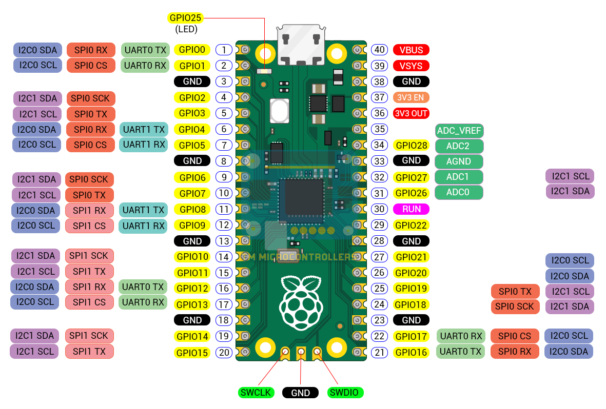
Suggested diagram labels: Digital GPIO, ADC1, ADC2, Touch, USB, UART, JTAG, strapping pins, flash/PSRAM-related pins, power, and onboard RGB LED.
ESP32-S3 Pinout Overview
The ESP32-S3 chip has 45 physical GPIO pins, numbered GPIO0 through GPIO21 and GPIO26 through GPIO48. Notice that GPIO22 through GPIO25 do not exist on the ESP32-S3. Not all 45 GPIOs are necessarily available on a development board. Some GPIO pins are connected internally to the SPI flash and PSRAM, while others may be assigned to onboard components.
| Feature | ESP32-S3 |
|---|---|
| GPIO | 45 physical GPIOs |
| ADC | 2 × 12-bit SAR ADCs, 20 channels |
| Touch | 14 capacitive touch GPIOs |
| UART | 3 controllers |
| I2C | 2 controllers |
| SPI | Multiple SPI interfaces |
| PWM | 8 LEDC PWM channels |
| Native USB | GPIO19 and GPIO20 |
| Strapping Pins | GPIO0, GPIO3, GPIO45, GPIO46 |
The ESP32 architecture also uses a flexible GPIO Matrix. This means peripherals such as UART, I2C, PWM, and many SPI signals can be routed to different GPIO pins instead of having a single permanently assigned pin. This flexibility is useful when designing an ESP32-S3 project, but it also means that a pinout diagram alone does not always tell you which pins you should actually use.
Interactive ESP32-S3 Pinout Diagram
ESP32-S3 GPIO Pin Reference
The following table summarizes the most important functions and restrictions of the ESP32-S3 GPIO pins.
| GPIO | Main Functions | Notes |
|---|---|---|
| GPIO0 | RTC GPIO | ⚠️ Strapping/BOOT pin |
| GPIO1 | ADC1_CH0, TOUCH1, RTC | Generally available |
| GPIO2 | ADC1_CH1, TOUCH2, RTC | Generally available |
| GPIO3 | ADC1_CH2, TOUCH3, RTC | ⚠️ Strapping pin |
| GPIO4 | ADC1_CH3, TOUCH4, RTC | Generally available |
| GPIO5 | ADC1_CH4, TOUCH5, RTC | Generally available |
| GPIO6 | ADC1_CH5, TOUCH6, RTC | Generally available |
| GPIO7 | ADC1_CH6, TOUCH7, RTC | Generally available |
| GPIO8 | ADC1_CH7, TOUCH8, RTC | Generally available |
| GPIO9 | ADC1_CH8, TOUCH9, RTC, FSPI | Generally available |
| GPIO10 | ADC1_CH9, TOUCH10, RTC, FSPI | Generally available |
| GPIO11 | ADC2_CH0, TOUCH11, RTC, FSPI | Generally available |
| GPIO12 | ADC2_CH1, TOUCH12, RTC, FSPI | Generally available |
| GPIO13 | ADC2_CH2, TOUCH13, RTC, FSPI | Generally available |
| GPIO14 | ADC2_CH3, TOUCH14, RTC, FSPI | Generally available |
| GPIO15 | ADC2_CH4, RTC, U0RTS | Generally available |
| GPIO16 | ADC2_CH5, RTC, U0CTS | Generally available |
| GPIO17 | ADC2_CH6, RTC, U1TXD | Generally available |
| GPIO18 | ADC2_CH7, RTC, U1RXD | Generally available |
| GPIO19 | ADC2_CH8, USB D-, RTC | ⚠️ Native USB |
| GPIO20 | ADC2_CH9, USB D+, RTC | ⚠️ Native USB |
| GPIO21 | RTC GPIO | Generally available |
| GPIO26–32 | SPI flash/PSRAM | ❌ Normally reserved for memory |
| GPIO33–37 | SPI flash/PSRAM functions | ⚠️ Availability depends on memory configuration |
| GPIO38 | General GPIO | ⚠️ RGB LED on DevKitC-1 v1.1 |
| GPIO39 | MTCK / JTAG | ⚠️ JTAG pin |
| GPIO40 | MTDO / JTAG | ⚠️ JTAG pin |
| GPIO41 | MTDI / JTAG | ⚠️ JTAG pin |
| GPIO42 | MTMS / JTAG | ⚠️ JTAG pin |
| GPIO43 | UART0 TX | ⚠️ Serial/programming output |
| GPIO44 | UART0 RX | ⚠️ Serial/programming input |
| GPIO45 | General GPIO | ⚠️ Strapping pin |
| GPIO46 | General GPIO | ⚠️ Strapping pin |
| GPIO47 | General GPIO | Generally available |
| GPIO48 | General GPIO | ⚠️ RGB LED on original DevKitC-1 |
Keep in mind that the exact availability of GPIO33 through GPIO37 depends on the ESP32-S3 module and its flash/PSRAM configuration. Always check the module fitted to your development board before using these pins.
Best ESP32-S3 GPIO Pins to Use
If you simply need GPIO pins for LEDs, buttons, sensors, relays, and similar devices, it is generally best to avoid pins involved in boot configuration, flash/PSRAM, USB, and debugging. For a typical ESP32-S3 development board, the following pins are among the easier GPIOs to work with:
- GPIO1
- GPIO2
- GPIO4 to GPIO18
- GPIO21
- GPIO47
These are not the only GPIO pins you can use. They are simply good starting choices because they normally do not interfere with the ESP32-S3 boot process or its USB and JTAG interfaces. GPIO38 and GPIO48 can also be usable depending on the board revision. On the ESP32-S3-DevKitC-1, however, one of these pins is connected to the onboard addressable RGB LED.
ESP32-S3 Pins to Avoid or Use With Caution
Some ESP32-S3 pins can still be used as GPIOs but have important secondary functions.
| Pins | Reason for Caution |
|---|---|
| GPIO0, GPIO3, GPIO45, GPIO46 | Strapping pins sampled during reset |
| GPIO19, GPIO20 | Native USB D- and D+ |
| GPIO26–32 | Normally connected to SPI flash/PSRAM |
| GPIO33–37 | May be used by Octal flash/PSRAM |
| GPIO39–42 | JTAG debugging interface |
| GPIO43, GPIO44 | UART0 serial interface |
Using one of these pins does not necessarily cause a problem. The important point is to understand what functionality you may lose or what boot behavior your external circuit might affect.
ESP32-S3 Strapping Pins
The ESP32-S3 has four strapping pins:
- GPIO0
- GPIO3
- GPIO45
- GPIO46
Strapping pins are read by the ESP32-S3 during reset to determine certain startup settings. After the chip has booted, they can generally function as normal GPIO pins. The most familiar example is GPIO0. Holding GPIO0 at the appropriate level during reset can place the ESP32-S3 into its firmware download mode. This is what the BOOT button on many ESP32-S3 boards controls. Because the state of a strapping pin matters during reset, avoid connecting external circuits that force these pins to an inappropriate logic level during startup.
ESP32-S3 ADC Pins
The ESP32-S3 contains two 12-bit SAR ADC peripherals providing a total of 20 analog input channels.
ADC1 Pins
| GPIO | ADC Channel |
|---|---|
| GPIO1 | ADC1_CH0 |
| GPIO2 | ADC1_CH1 |
| GPIO3 | ADC1_CH2 |
| GPIO4 | ADC1_CH3 |
| GPIO5 | ADC1_CH4 |
| GPIO6 | ADC1_CH5 |
| GPIO7 | ADC1_CH6 |
| GPIO8 | ADC1_CH7 |
| GPIO9 | ADC1_CH8 |
| GPIO10 | ADC1_CH9 |
ADC2 Pins
| GPIO | ADC Channel |
|---|---|
| GPIO11 | ADC2_CH0 |
| GPIO12 | ADC2_CH1 |
| GPIO13 | ADC2_CH2 |
| GPIO14 | ADC2_CH3 |
| GPIO15 | ADC2_CH4 |
| GPIO16 | ADC2_CH5 |
| GPIO17 | ADC2_CH6 |
| GPIO18 | ADC2_CH7 |
| GPIO19 | ADC2_CH8 |
| GPIO20 | ADC2_CH9 |
For new designs, ADC1 is generally the better choice when you have free pins available. Also remember that the ESP32-S3 GPIO voltage is 3.3 V. Never apply a 5 V analog signal directly to an ADC pin. Use a voltage divider or appropriate signal-conditioning circuit when measuring higher voltages. If accuracy is important, Espressif also recommends filtering the ADC input. A small capacitor close to the ADC input can reduce noise, and software calibration can further improve measurement accuracy.
ESP32-S3 Touch Pins
The ESP32-S3 provides 14 capacitive-touch GPIO pins. These can detect changes in capacitance caused by a finger approaching or touching an electrode.
| Touch Channel | GPIO |
|---|---|
| TOUCH1 | GPIO1 |
| TOUCH2 | GPIO2 |
| TOUCH3 | GPIO3 |
| TOUCH4 | GPIO4 |
| TOUCH5 | GPIO5 |
| TOUCH6 | GPIO6 |
| TOUCH7 | GPIO7 |
| TOUCH8 | GPIO8 |
| TOUCH9 | GPIO9 |
| TOUCH10 | GPIO10 |
| TOUCH11 | GPIO11 |
| TOUCH12 | GPIO12 |
| TOUCH13 | GPIO13 |
| TOUCH14 | GPIO14 |
Touch inputs are useful for projects such as touch buttons, sliders, control panels, and proximity sensors without requiring a mechanical switch.
ESP32-S3 PWM Pins
PWM on the ESP32-S3 is much more flexible than on traditional Arduino boards. Instead of having a small number of pins permanently designated as PWM pins, the ESP32-S3 can route the LEDC PWM peripheral to suitable GPIO pins through the GPIO Matrix.
The ESP32-S3 provides 8 LEDC channels. These can be used for applications including:
- LED brightness control
- RGB LEDs
- Motor speed control
- Servo control
- Generating periodic digital signals
This means there is no simple list of dedicated "PWM pins" like there is on an Arduino Uno. Instead, choose a suitable output-capable GPIO that is not required for another important function.
ESP32-S3 I2C Pins
The ESP32-S3 provides two I2C controllers. Thanks to the GPIO Matrix, the SDA and SCL signals can be assigned to different GPIO pins. Therefore, the ESP32-S3 does not have only one mandatory pair of I2C pins. For example, you could connect an I2C sensor using GPIO8 for SDA and GPIO9 for SCL:
#include <Wire.h>

#define SDA_PIN 8
#define SCL_PIN 9

void setup() {
  Wire.begin(SDA_PIN, SCL_PIN);
}

void loop() {
}
If a development board or Arduino board definition specifies default I2C pins, calling Wire.begin() without arguments may use those defaults. Explicitly specifying SDA and SCL makes your intended pin assignment clear.
ESP32-S3 SPI Pins
The ESP32-S3 contains multiple SPI interfaces. Some SPI interfaces are used internally for flash and PSRAM, while others can be used to connect external devices such as:
- TFT displays
- SD cards
- Ethernet controllers
- ADC and DAC modules
- Radio transceivers
SPI signals can often be routed through the GPIO Matrix, so external SPI devices do not always need to use a single fixed pin configuration. However, avoid blindly selecting GPIO26 through GPIO32 because these pins are normally associated with the ESP32-S3's flash and PSRAM interfaces.
ESP32-S3 UART Pins
The ESP32-S3 has three UART controllers. UART signals can normally be routed to different GPIOs, making it possible to choose convenient pins for serial devices such as GPS modules, fingerprint sensors, GSM modules, and other microcontrollers. Two pins have particularly important default UART0 functions:
| GPIO | Function |
|---|---|
| GPIO43 | U0TXD |
| GPIO44 | U0RXD |
GPIO43 and GPIO44 can be reused, but doing so may interfere with serial console output or other UART0 functions depending on how the board and firmware are configured.
ESP32-S3 Native USB Pins
Unlike the original ESP32, the ESP32-S3 includes native USB functionality.
| GPIO | USB Function |
|---|---|
| GPIO19 | USB D- |
| GPIO20 | USB D+ |
These pins support the ESP32-S3's native USB functionality, including USB Serial/JTAG and USB OTG applications. GPIO19 and GPIO20 can be configured as normal GPIOs, but doing so prevents them from simultaneously serving as the native USB data pins. If your board uses the ESP32-S3 USB connector for programming, debugging, or USB device functionality, leave these GPIOs assigned to USB.
ESP32-S3 JTAG Pins
The traditional JTAG interface is available through GPIO39 to GPIO42:
| GPIO | JTAG Signal |
|---|---|
| GPIO39 | MTCK |
| GPIO40 | MTDO |
| GPIO41 | MTDI |
| GPIO42 | MTMS |
If you are not using external JTAG debugging, these pins may be available for other GPIO functions. However, keeping them free can be useful during firmware development and debugging. The ESP32-S3 also supports USB Serial/JTAG through GPIO19 and GPIO20, so debugging does not always require the traditional four-pin JTAG connection.
ESP32-S3 Flash and PSRAM Pins
Flash and PSRAM are where ESP32-S3 pin selection becomes particularly board-dependent. GPIO26 through GPIO32 are normally used for communication with SPI flash and PSRAM and should not be treated as general-purpose GPIOs.
GPIO33 through GPIO37 may also be required when the ESP32-S3 uses Octal flash or Octal PSRAM. The exact GPIO availability therefore depends on the ESP32-S3 chip or module installed on your board. For example, some ESP32-S3-WROOM configurations use GPIO35, GPIO36, and GPIO37 internally. Those pins cannot then be used to connect external peripherals even if they appear in a generic ESP32-S3 GPIO table. This is why you should check both the ESP32-S3 chip pinout and the documentation for your exact ESP32-S3 module or development board.
ESP32-S3-DevKitC-1 RGB LED Pin
The ESP32-S3-DevKitC-1 includes an onboard addressable RGB LED, but there is an important difference between board revisions.
| DevKitC-1 Version | RGB LED GPIO |
|---|---|
| Original revision | GPIO48 |
| v1.1 | GPIO38 |
If an RGB LED example does not work despite using the correct ESP32-S3 board definition, check which DevKitC-1 revision you own. This distinction is also worth remembering when connecting another peripheral to GPIO38 or GPIO48.
ESP32-S3 Power Pins
On the ESP32-S3-DevKitC-1 you will also find several power-related pins:
| Pin | Description |
|---|---|
| 3V3 | 3.3 V supply rail |
| 5V | 5 V supply rail |
| G / GND | Ground |
| RST / EN | ESP32-S3 enable/reset |
The ESP32-S3 GPIOs themselves use 3.3 V logic. Do not connect a 5 V logic output directly to an ESP32-S3 GPIO unless the signal is converted to a safe voltage using a voltage divider, level shifter, or another appropriate circuit.
ESP32-S3 GPIO Example with Arduino
GPIO programming on the ESP32-S3 works much like other Arduino-compatible microcontrollers. For example, the following sketch toggles an LED connected to GPIO4:
#define LED_PIN 4

void setup() {
  pinMode(LED_PIN, OUTPUT);
}

void loop() {
  digitalWrite(LED_PIN, HIGH);
  delay(500);

  digitalWrite(LED_PIN, LOW);
  delay(500);
}
GPIO4 is a convenient example because it is a general-purpose pin while also supporting ADC and capacitive-touch functionality. The same physical pin can perform different functions depending on how the peripheral registers or Arduino libraries configure it.
ESP32-S3 vs ESP32 Pinout
If you are moving from the original ESP32 to the ESP32-S3, do not assume that existing pin assignments can be copied directly. The two chips have substantially different GPIO layouts. The ESP32-S3 also introduces native USB on GPIO19 and GPIO20 and has different ADC, touch, flash, PSRAM, and strapping-pin assignments. At the same time, the ESP32-S3 provides considerably more usable GPIO resources, making it better suited for projects requiring many sensors, displays, buttons, or other peripherals. Always use an ESP32-S3-specific pinout when designing an ESP32-S3 circuit rather than referring to a standard ESP32 pinout diagram.
Frequently Asked Questions
How many GPIO pins does the ESP32-S3 have?
The ESP32-S3 chip has 45 physical GPIO pins: GPIO0 through GPIO21 and GPIO26 through GPIO48. The exact number available on a development board is smaller because some GPIOs may be connected to flash, PSRAM, USB, or onboard peripherals.
What are the best GPIO pins to use on the ESP32-S3?
For ordinary digital peripherals, GPIO1, GPIO2, GPIO4 through GPIO18, GPIO21, and GPIO47 are generally convenient choices. Always check the exact development board because onboard hardware can reserve additional pins.
Which ESP32-S3 pins should I avoid?
GPIO26 through GPIO32 should normally be avoided because they are associated with flash/PSRAM. GPIO0, GPIO3, GPIO45, and GPIO46 are strapping pins. GPIO19 and GPIO20 are used for native USB, while GPIO39 through GPIO42 are associated with JTAG.
Which ESP32-S3 pins support ADC?
GPIO1 through GPIO10 belong to ADC1, while GPIO11 through GPIO20 belong to ADC2. Together they provide 20 ADC channels.
Which ESP32-S3 pins support touch?
GPIO1 through GPIO14 provide the ESP32-S3's capacitive-touch inputs.
Which ESP32-S3 pins are used for USB?
GPIO19 is USB D- and GPIO20 is USB D+. Reassigning these pins as ordinary GPIOs disables their use for the native USB interface.
Does the ESP32-S3 have fixed I2C pins?
No. The ESP32-S3 GPIO Matrix allows I2C SDA and SCL to be assigned to suitable GPIO pins. Development-board definitions may provide default pins, but they can usually be changed in software.
Can any ESP32-S3 GPIO generate PWM?
PWM signals from the LEDC peripheral can be routed to suitable output-capable GPIOs. The ESP32-S3 has eight LEDC PWM channels rather than a fixed set of Arduino-style PWM pins.
Why are GPIO22 through GPIO25 missing?
The ESP32-S3 GPIO numbering is not continuous. Its physical GPIO ranges are GPIO0–GPIO21 and GPIO26–GPIO48, so GPIO22, GPIO23, GPIO24, and GPIO25 simply do not exist on the chip.
Conclusion
The ESP32-S3 provides a flexible GPIO system with plenty of pins for sensors, displays, communications interfaces, and other peripherals. Its GPIO Matrix makes interfaces such as I2C, UART, SPI, and PWM much less dependent on fixed pin assignments than on many conventional microcontrollers.
The main pins to pay attention to are the GPIO0, GPIO3, GPIO45, and GPIO46 strapping pins, GPIO19 and GPIO20 USB pins, GPIO39 through GPIO42 JTAG pins, and the GPIOs reserved for flash and PSRAM. Once these restrictions are understood, choosing pins for an ESP32-S3 project becomes relatively straightforward.
If you are working with a specific ESP32-S3 development board, remember that the board itself may reserve additional GPIOs for LEDs, displays, cameras, PSRAM, or other onboard hardware. Always combine this ESP32-S3 GPIO reference with the schematic or pinout of your exact board.