The Raspberry Pi Pico 2 is a microcontroller development board and the successor to the original Raspberry Pi Pico. It features the RP2350, a 32-bit dual-core microcontroller that can run either Arm Cortex-M33 or Hazard3 RISC-V processors at speeds up to 150 MHz.
The Raspberry Pi Pico 2 has a 40-pin header with 26 exposed GPIO pins, including three analog inputs. It also includes 520 KB of SRAM and 4 MB of onboard flash memory. Despite the upgraded microcontroller, the Pico 2 retains the same physical pinout as the original Pico, making it largely compatible with existing Pico hardware and accessories.
Like the original Pico, the Pico 2 can run code using the Pico C/C++ SDK, Arduino IDE, or MicroPython. Its GPIO pins operate at a 3.3 V logic level.
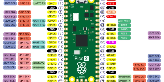
Interactive Pinout
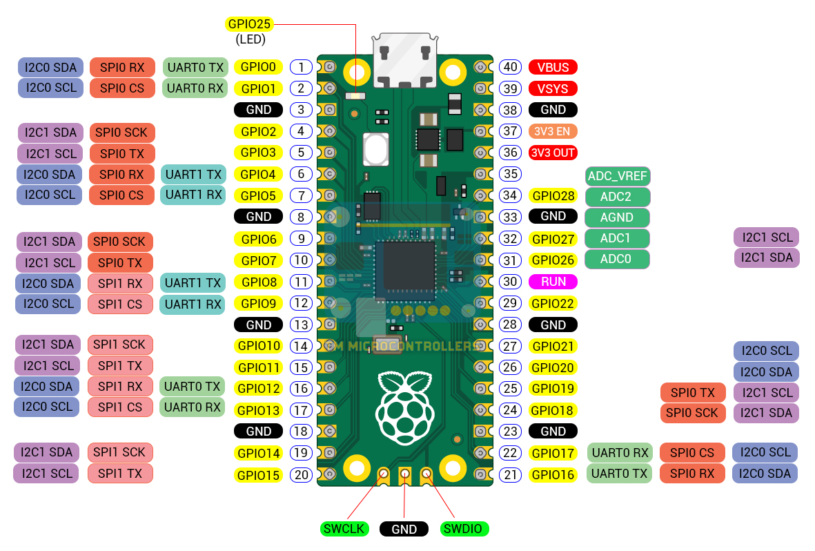
Raspberry Pi Pico 2 Pinout Description
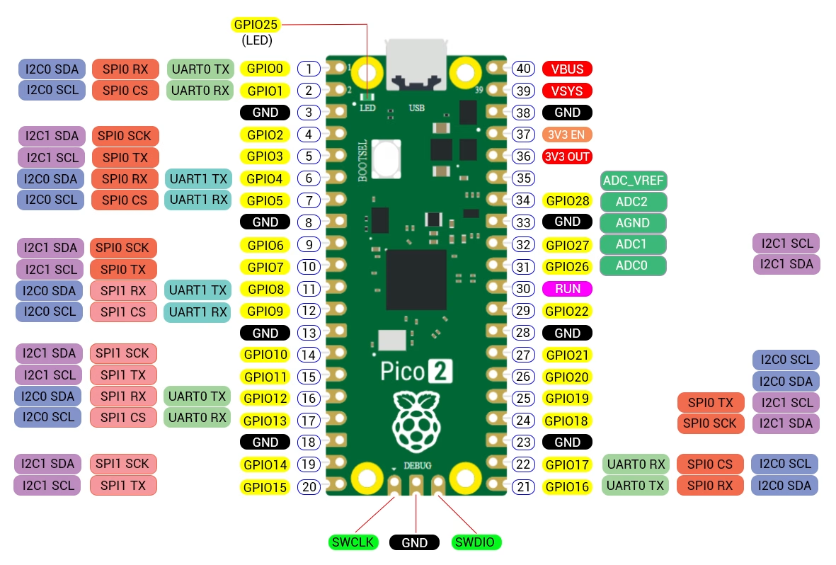
Most of the GPIO pins on the Raspberry Pi Pico 2 can perform several different functions. In general, these functions include GPIO, UART, I2C, ADC, PWM, PIO, and SPI. The Pico 2 uses the same 40-pin layout as the original Pico. Therefore, projects that connect to GP0 through GP28, the power pins, or the RUN pin can generally use the Pico 2 without changing the wiring.
General Purpose Pins
The Pico 2 exposes 26 GPIO pins on its headers. These are GP0 to GP22 and GP26 to GP28. Most GPIO pins can also serve as UART, I2C, SPI, PWM, or programmable I/O pins. The RP2350 provides three Programmable I/O or PIO blocks, compared with two on the original RP2040. Together, these provide 12 PIO state machines for implementing custom digital interfaces.
Analog Input Pins
Three ADC inputs are available directly on the Pico 2 headers:
- GP26 – ADC0
- GP27 – ADC1
- GP28 – ADC2
The RP2350 contains a 12-bit analog-to-digital converter. Although the RP2350A provides four ADC-capable GPIOs internally, only three are exposed as GPIO pins on the Pico 2 header.
Power Pins
The Raspberry Pi Pico 2 provides several pins for powering the board and connected peripherals:
- VBUS – USB input voltage, normally around 5 V when USB is connected
- VSYS – Main system power input
- 3V3(OUT) – Regulated 3.3 V output
- 3V3_EN – Enables or disables the onboard 3.3 V regulator
- ADC_VREF – Reference voltage for the ADC
- GND / AGND – Digital and analog ground connections
SWD Pins
The SWD pins are used to program and debug the Raspberry Pi Pico 2 using the Serial Wire Debug interface. The three dedicated pads provide SWCLK, GND, and SWDIO.
Raspberry Pi Pico vs. Pico 2 Pinout
One of the advantages of upgrading from the original Pico to the Pico 2 is that the two boards use the same physical pin layout. GP0 is still on pin 1, GP1 is on pin 2, GP26/ADC0 is on pin 31, and the power and ground pins remain in the same locations.
However, the RP2350 adds several capabilities that are not available on the RP2040. These include an additional PIO block, additional alternate GPIO functions, and the RP2350's high-speed HSTX peripheral. These advanced functions do not change the physical header layout.
This means that, for most existing Raspberry Pi Pico projects, you can replace the original Pico with a Pico 2 without changing the circuit wiring.
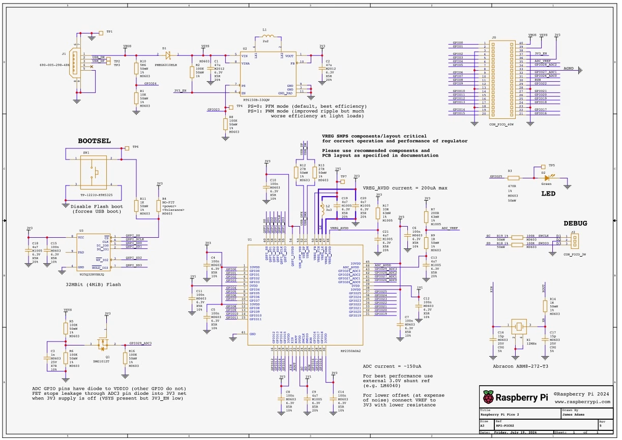
Raspberry Pi Pico 2 Schematic
(Click to view larger image)