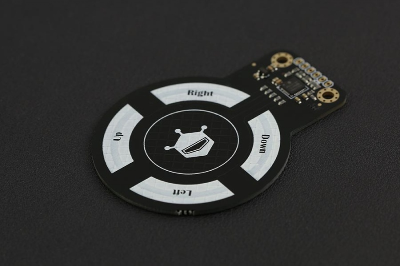
The APDS-9960 is probably better known as a gesture sensor. It can detect hand movements such as left, right, up, and down, while also providing proximity sensing. However, the same small module also contains red, green, blue, and clear light-sensing channels. This means we can also use the APDS-9960 as a color sensor.
There is an important catch. The APDS-9960 does not simply look at an object and return a value such as "red" or "green." It measures the red, green, blue, and overall light reaching the sensor. When we use it to identify the color of an object, what we are really measuring is light reflected from that object's surface.
This makes the light source, distance, and positioning of the sensor surprisingly important. In this tutorial, I will connect an APDS-9960 to an ESP32, read its RGB values, and test it on real colored objects. I will also show why getting consistent color detection requires more than just reading three numbers from the sensor.
How the APDS-9960 Detects Color
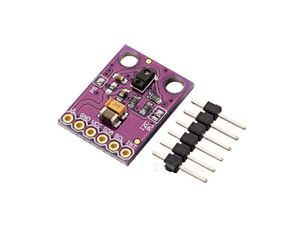
The APDS-9960 contains separate sensing channels for:
- Red light
- Green light
- Blue light
- Clear or overall light intensity
The sensor converts the amount of light detected by each channel into digital values that can be read by the ESP32 through I2C.
For example, when a red object is illuminated with white light, the surface tends to reflect more of the red wavelengths while absorbing more of the other visible wavelengths. Ideally, the red value measured by the APDS-9960 will therefore be higher than the green and blue values.
The basic arrangement looks like this:
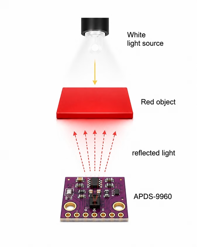
This distinction is important. We are not directly measuring an intrinsic "color value" stored inside the object. We are measuring reflected light. Change the light source or the physical arrangement and the measured values can change too.
Why the Light Source Matters
For an object to be measured, there must first be enough visible light falling on it. The object then reflects part of that light toward the APDS-9960.
During my initial tests, simply placing a colored plastic folder near the APDS-9960 without deliberate illumination produced very low RGB values. Illuminating the plastic with the flashlight from a phone made the differences between the channels much easier to observe.
This gives us our first important rule when using the APDS-9960 for color detection:
Use a consistent light source.
A phone flashlight is perfectly adequate for experimentation, but a permanent project would be better served by one or more fixed white LEDs mounted at a known distance and angle from the target.
Relying entirely on room lighting can create problems. The readings taken during daytime near a window may be different from readings taken at night under a warm-white lamp. Even two apparently white light sources can have significantly different spectral characteristics.
The APDS-9960 does contain an integrated infrared LED, but that LED is intended for its proximity and gesture functions. Infrared illumination is not a substitute for a visible white light source when we want to determine the visible color of an object.
Why Sensor Positioning Matters
The second thing that became obvious during testing was that positioning matters almost as much as illumination.
Changing the distance between the APDS-9960 and the object changes how much reflected light reaches the sensor. Changing the angle can also change the relative RGB readings, particularly when testing smooth or glossy materials.
There are actually several distances and angles that we should try to keep constant:
- Distance from the APDS-9960 to the object
- Distance from the light source to the object
- Angle of the sensor relative to the object
- Angle of the light source relative to the object
The effect becomes even more noticeable with transparent or semi-transparent objects. Light can travel through the material, reflect from whatever is behind it, and eventually reach the sensor. In this case, the background effectively becomes part of the measurement.
If your final project needs repeatable color detection, consider building a small fixture or enclosure that holds the sensor, light source, and target at fixed positions.
Connecting the APDS-9960 to ESP32
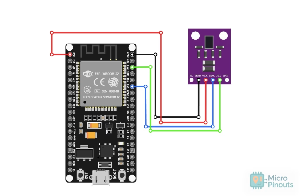
The APDS-9960 communicates through I2C. For a typical ESP32 development board, GPIO21 and GPIO22 can be used as SDA and SCL respectively.
| APDS-9960 | ESP32 |
|---|---|
| VCC | 3.3 V |
| GND | GND |
| SDA | GPIO21 |
| SCL | GPIO22 |
GPIO21 and GPIO22 are only conventional I2C pins on the ESP32. Other GPIO pins can be assigned in software if necessary.
Also check the particular APDS-9960 breakout board you are using before applying power. The bare APDS-9960 is a low-voltage device, while some breakout boards add regulators or level shifting. For an unknown generic module, using 3.3 V is the safer starting point.
The APDS-9960 has a fixed I2C address of 0x39.
Installing the APDS-9960 Library
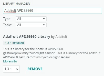
For this experiment, I used the Adafruit APDS9960 Library. In the Arduino IDE, open the Library Manager and search for:
Adafruit APDS9960
Install the library together with any dependencies requested by the Arduino IDE.
ESP32 APDS-9960 Color Sensor Code
The following sketch initializes the sensor, waits until new color data is available, and then reads the red, green, blue, and clear channels.
I also calculate normalized RGB values, which we will discuss shortly.
#include <Wire.h>
#include <Adafruit_APDS9960.h>

#define SDA_PIN 21
#define SCL_PIN 22

Adafruit_APDS9960 apds;

void setup()
{
  Serial.begin(115200);
  delay(1000);

  Serial.println();
  Serial.println("APDS-9960 Color Sensor Test");

  Wire.begin(SDA_PIN, SCL_PIN);

  if (!apds.begin())
  {
    Serial.println("APDS-9960 not found.");
    Serial.println("Check wiring and power.");

    while (1)
    {
      delay(1000);
    }
  }

  Serial.println("APDS-9960 detected.");

  // Increase sensitivity for reflected-light measurements
  apds.setADCIntegrationTime(100);
  apds.setADCGain(APDS9960_AGAIN_16X);

  // Enable RGB / ambient-light sensing
  apds.enableColor(true);
}

void loop()
{
  uint16_t red;
  uint16_t green;
  uint16_t blue;
  uint16_t clear;

  while (!apds.colorDataReady())
  {
    delay(5);
  }

  apds.getColorData(&red, &green, &blue, &clear);

  Serial.println("-------------------------");

  Serial.print("R: ");
  Serial.println(red);

  Serial.print("G: ");
  Serial.println(green);

  Serial.print("B: ");
  Serial.println(blue);

  Serial.print("C: ");
  Serial.println(clear);

  if (clear > 0)
  {
    float rNorm = (float)red / clear;
    float gNorm = (float)green / clear;
    float bNorm = (float)blue / clear;

    Serial.print("Normalized: R=");
    Serial.print(rNorm, 3);

    Serial.print(" G=");
    Serial.print(gNorm, 3);

    Serial.print(" B=");
    Serial.println(bNorm, 3);
  }

  delay(500);
}
I increased the ADC integration time and selected 16× gain because reflected-light measurements can sometimes be weak. A longer integration time allows the sensor to collect light for longer, while the higher gain increases sensitivity.
These values are not mandatory. In a brightly illuminated setup, the sensor may produce very large readings or saturate. If this happens, reduce the gain or integration time.
Testing a Red Plastic Folder
For my first test, I placed a red plastic folder in front of the APDS-9960 and illuminated it using the flashlight from a phone.
The ESP32 reported:
R: 7
G: 3
B: 3
C: 13
Normalized: R=0.538 G=0.231 B=0.231
The absolute values are quite small, but the important part is the relationship between the channels. The red channel is clearly stronger than both green and blue.
| Channel | Raw Value | Normalized Value |
|---|---|---|
| Red | 7 | 0.538 |
| Green | 3 | 0.231 |
| Blue | 3 | 0.231 |
Even this simple experiment shows that the APDS-9960 can distinguish a strongly red surface.
Testing a Green Semi-Transparent Folder
I then replaced the red folder with a green semi-transparent plastic folder while using the same phone flashlight.
This time, I obtained:
R: 11
G: 29
B: 27
C: 72
Normalized: R=0.153 G=0.403 B=0.375
The green channel is the highest:
| Channel | Raw Value | Normalized Value |
|---|---|---|
| Red | 11 | 0.153 |
| Green | 29 | 0.403 |
| Blue | 27 | 0.375 |
However, notice that the blue reading is also very close to green. The result is therefore not nearly as clear-cut as our red sample.
There are several possible contributors. The folder is semi-transparent, so some of the measured light can come through the plastic rather than only being reflected from its surface. The background behind the plastic can therefore affect the reading. The spectrum of the phone flashlight also affects the amount of red, green, and blue energy available for reflection or transmission.
The result still looks significantly different from the red sample, but it demonstrates why a single rule such as "the largest RGB value is the color" can easily become unreliable.
Why Normalize the RGB Values?
Suppose we move the light closer to the object. The raw red, green, and blue values may all increase even though the object's color has not changed.
One simple way of reducing the effect of overall brightness is to divide each RGB channel by the clear-channel reading:


For our red folder:


The resulting ratios make the dominance of red easy to see.
Normalization is useful for simple object classification, but it should not be confused with full color calibration. It cannot completely compensate for a different light source, different viewing angle, reflections, transparency, or other changes to the optical setup.
Also be careful when the clear value is very small. For example, when C is only 10 or 20 counts, a change of just one ADC count represents a significant change in the calculated ratio. It is better to improve the illumination or sensor sensitivity than to build a classifier from extremely weak signals.
Raw RGB Values Versus Object Color
A common mistake when building a color detector is to assume that an object can be classified simply by finding the largest channel:
if (red > green && red > blue)
{
  // Must be red?
}
This can work for strongly separated colors under controlled conditions, but our green-folder experiment shows the problem. Green was 29 while blue was 27. Those values are too close for me to confidently build a universal rule around them.
A more practical system should first collect several measurements of every object or color that needs to be recognized.
For example:
| Sample | R/C | G/C | B/C |
|---|---|---|---|
| Red plastic | 0.538 | 0.231 | 0.231 |
| Green translucent plastic | 0.153 | 0.403 | 0.375 |
| Blue sample | Measure | Measure | Measure |
| Yellow sample | Measure | Measure | Measure |
| White sample | Measure | Measure | Measure |
| Black sample | Measure | Measure | Measure |
Take multiple measurements instead of relying on only one reading. From these samples, you can establish ranges or thresholds that are appropriate for your particular hardware and mechanical arrangement.
Using a Confidence Margin
For simple experiments, another improvement is to require the winning color channel to exceed the others by a minimum amount.
For example:
String classifyColor(float r, float g, float b)
{
  const float margin = 0.08;

  if ((r - g > margin) && (r - b > margin))
    return "RED";

  if ((g - r > margin) && (g - b > margin))
    return "GREEN";

  if ((b - r > margin) && (b - g > margin))
    return "BLUE";

  return "UNSURE";
}
Our red folder would easily satisfy this type of test. The green translucent folder probably would not because its green and blue readings are very close. Returning UNSURE is usually better than confidently returning the wrong color.
The value of 0.08 here is only an example. A real threshold should come from measurements of your actual objects.
Improving APDS-9960 Color Detection
If I were turning this breadboard experiment into a real color-sensing project, I would make several changes.
1. Use a Fixed White LED
Instead of holding a phone flashlight by hand, mount a white LED at a fixed angle and distance from the target.
This gives every object approximately the same illumination and makes calibration much more meaningful.
2. Keep the Object at a Fixed Distance
A mechanical stop, slot, guide, or enclosure can make sure every sample appears at the same distance from the APDS-9960.
This is particularly useful for projects such as a color sorter where objects always travel through the same sensing position.
3. Control the Viewing Angle
Glossy plastic can produce strong specular reflections. A small change in angle may send much more or much less reflected light directly into the sensor.
Mounting the sensor and illumination mechanically eliminates much of this variation.
4. Control the Background
This becomes important when testing thin or translucent objects. Place an opaque and consistent backing behind the object if possible.
A white, black, or otherwise known background can produce much more repeatable measurements than whatever happens to be sitting behind the test object.
5. Average Several Measurements
Instead of classifying an object from one sample, take perhaps 5 to 20 readings and calculate an average.
This reduces the effect of occasional noisy readings and small changes in reflected light.
6. Avoid Extremely Low Signal Levels
If the clear reading is only a few counts, normalized values can become unstable. Increase illumination, increase integration time, increase gain, or move the object closer until the sensor produces a healthier signal.
At the other extreme, avoid saturating the sensor. If values approach their maximum range, reduce gain, integration time, or illumination.
Is the APDS-9960 a Good Color Sensor?
After experimenting with it, I would say yes, with some qualifications.
The APDS-9960 can definitely distinguish differences in reflected color. Our red sample produced a strongly dominant red channel, while the green sample produced a completely different RGB distribution.
However, I would use it primarily for color classification rather than precision color measurement.
Good applications include:
- Detecting whether an object is red, green, or blue
- Sorting a limited set of known colored objects
- Identifying colored markers or cards
- Educational experiments involving reflected light
- Adding simple color awareness to an ESP32 project
I would not expect an uncalibrated APDS-9960 sitting openly on a breadboard to accurately identify arbitrary colors under arbitrary room lighting.
The key is to treat the sensor, illumination source, object position, and background as one optical measurement system.
Final Thoughts
The APDS-9960 is much more than a gesture sensor. Its red, green, blue, and clear channels allow it to become a surprisingly useful color detector when connected to an ESP32.
The most important lesson from my tests, however, is that color sensing is really an optical-system problem. The APDS-9960 measures the light that reaches it. When detecting the color of an object, this is largely light that has been reflected from that object.
As a result, the light source matters. Distance matters. Angle matters. The background matters, and the material itself matters.
For a quick experiment, a phone flashlight and a hand-held sample are enough to prove that the sensor responds differently to different colors. For a reliable project, use fixed white illumination and keep the sensor, object, and light source in repeatable positions.
With those conditions controlled, the APDS-9960 becomes a good candidate for simple color classification projects such as object sorters, colored-card interfaces, educational experiments, and other ESP32 projects where only a limited set of known colors needs to be identified.