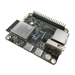
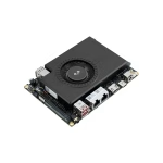
The ESP32-P4 is an unusual member of the ESP32 family: it has no integrated Wi-Fi or Bluetooth radio. On a microcontroller family best known for connected projects, that might seem like an odd omission. But Espressif designed the P4 for a different job. It combines RISC-V processors, camera and display interfaces, and hardware acceleration for graphics and multimedia applications.
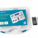
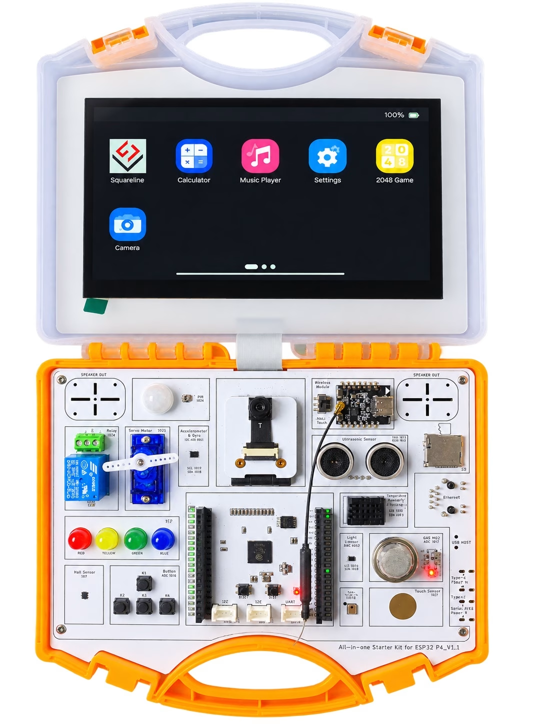
Elecrow's All-in-One ESP32-P4 Starter Kit turns those features into a learning platform. Elecrow integrates a 7-inch touchscreen, a 2-megapixel camera, audio hardware, and a common sensor board in one case. That lets you learn the software side without spending the first day wiring a display and several breakout modules.
We'll begin by identifying the kit, its board version, and its chip revision. Then we'll set up ESP-IDF, build a serial-output program, and control the onboard LED. We'll also explain what to expect from the display examples, how wireless expansion works, and which problems to check before blaming the firmware.
Disclosure: This article contains an affiliate link. We may earn a commission if you purchase through it, at no additional cost to you.
What’s Inside the Elecrow ESP32-P4 Starter Kit?
Elecrow sells this kit as model SEE00804D. The package contains the assembled starter kit in a portable case and a USB Type-C cable. The common board carries 16 sensor and output modules on one PCB, and the lid holds the touchscreen. A 2 MP wide-angle camera and audio hardware extend the kit beyond the usual LED-and-sensor exercises.
The display has a resolution of 1024 × 600 pixels and connects to the P4 over a two-lane MIPI DSI bus. That gives you enough space for a multi-page interface with controls, status information, and charts. A large display also adds software work that a character LCD doesn't need: panel initialization, frame buffers, graphics rendering, and touch input all have to match the actual hardware.
Starter Kit Specifications
| Specification | Elecrow SEE00804D |
|---|---|
| Main microcontroller | ESP32-P4: two high-performance RISC-V cores plus one low-power RISC-V core |
| HP CPU clock specified by Elecrow | Up to 360 MHz |
| PSRAM | 16 MB in-package (Elecrow GitHub); 32 MB in some listings (ESP32-P4NRW32) |
| Flash | 16 MB NOR flash |
| Display | 7-inch IPS capacitive touchscreen, 1024 × 600, two-lane MIPI DSI (EK79007 driver IC) |
| Camera | 2 MP, 100° wide-angle, MIPI CSI |
| Audio | Onboard microphone and speaker |
| Common board | 16 integrated learning modules |
| Connectivity | No Wi-Fi or Bluetooth in the ESP32-P4; slot for an optional wireless module; 100 Mbps Ethernet (RJ45) |
| Interfaces | USB Type-C, USB Type-A, microSD (TF) slot, I²C and UART connectors, 2 × 20-pin GPIO header, MIPI CSI |
| Power input | 5 V through USB Type-C |
| Development software | ESP-IDF (Elecrow's guide uses 5.4.2) and Arduino course examples |
| Documented kit revisions | V1.0 and V1.1 |
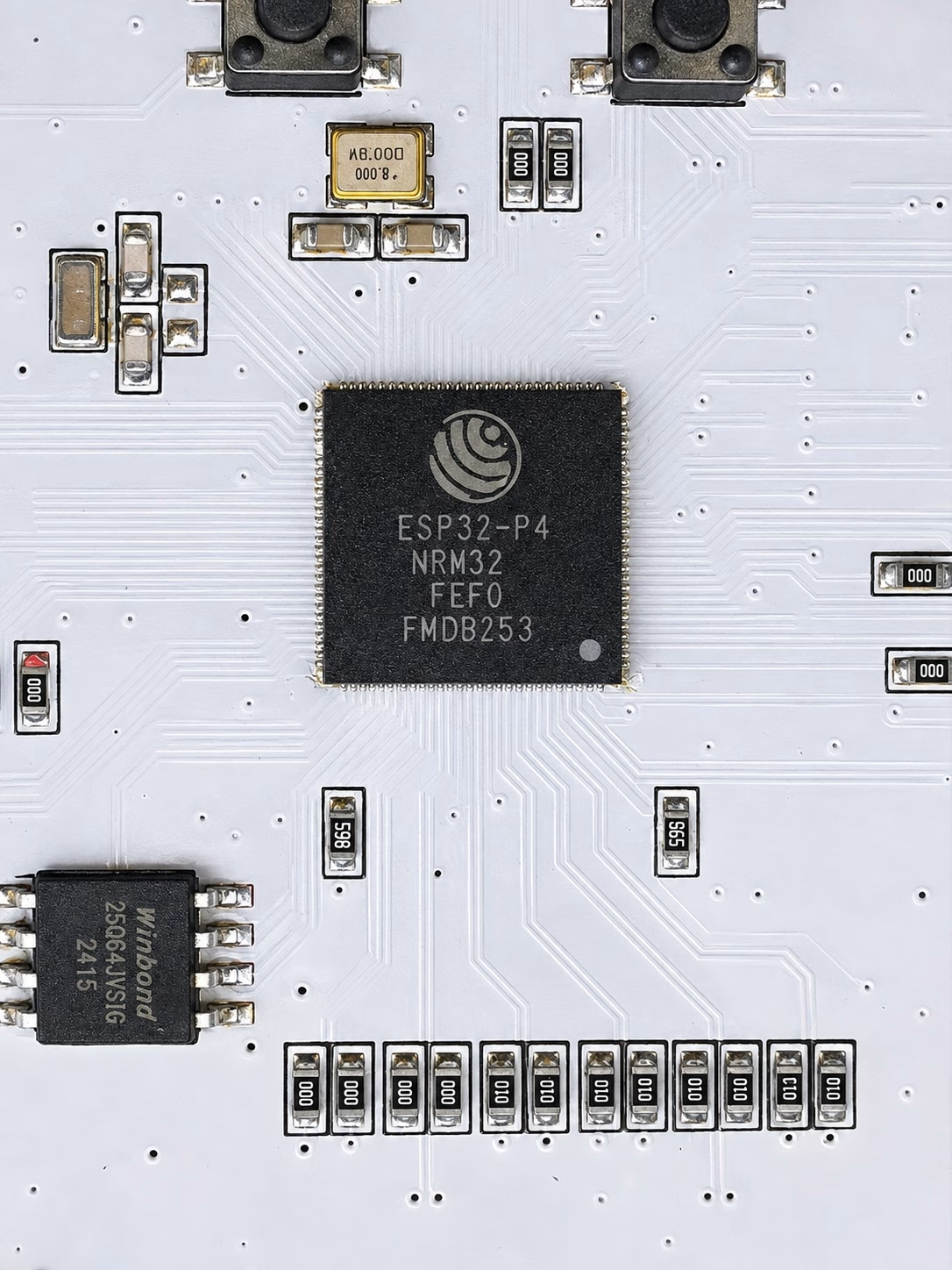
Elecrow's sources disagree on memory. Its GitHub README lists 16 MB of in-package PSRAM, while the launch specifications that CNX Software published name the ESP32-P4NRW32, which pairs the chip with 32 MB. The part number on your chip settles it: NRW16 indicates 16 MB of PSRAM, and NRW32 indicates 32 MB. With PSRAM enabled, the ESP-IDF boot log also reports the size it detects.
Onboard Sensors, Outputs, and Expansion
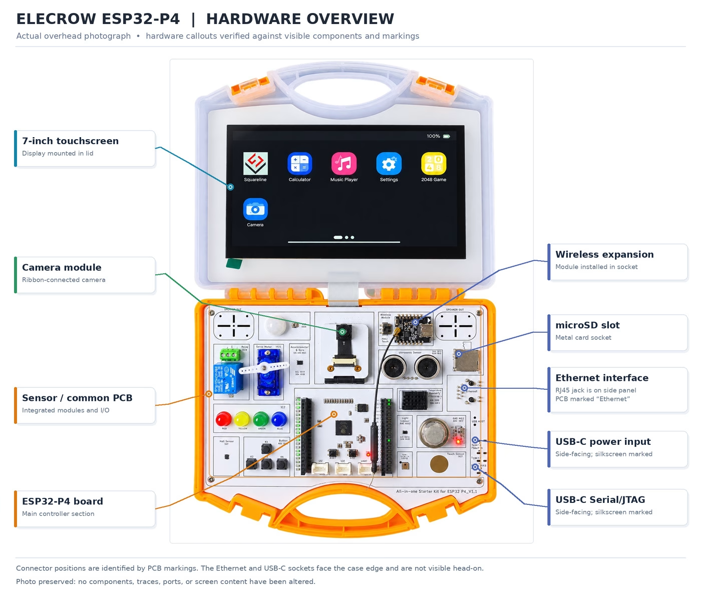
Elecrow routes the common board's connections in advance, which makes the basic exercises straightforward. Elecrow's pin list and course material identify these signals:
| Module or function | Connection | What it is useful for |
|---|---|---|
| LED (LED5) | GPIO5, active-low | Checking GPIO output |
| PIR motion sensor | GPIO24 | Digital input and motion events |
| Hall-effect sensor | GPIO7 (shares a selector switch with the touch sensor) | Detecting magnetic-field changes |
| Touch sensor | GPIO2 (shares a selector switch with the Hall sensor) | Reading touch input |
| User key | GPIO16 | Button input |
| Servo | GPIO25 | PWM servo control |
| MQ-2 gas sensor | GPIO17 | Gas and smoke detection |
| Relay | GPIO42 | Switched output control |
| DHT20 temperature/humidity sensor | I²C | Environmental measurements |
| BH1750 light sensor | I²C | Light-level measurements |
The board also carries an ultrasonic distance sensor, an LSM6DS3 accelerometer and gyroscope, a WS2814 RGBW LED, a microphone, and a speaker, and Elecrow's lessons cover each one. Confirm their pins against the board markings and schematic before you write your own code. Elecrow's ultrasonic lesson, for example, lists two different pin pairs in different places.
One hardware detail catches people out: the touch and Hall sensors share a toggle switch next to the wireless-module slot. Elecrow's lessons require the switch in its Hall/touch position before either sensor will work.
A useful ESP32-P4 detail: ESP-IDF assigns GPIO24 and GPIO25 to USB-JTAG by default, and reconfiguring either as an ordinary GPIO disables that debug function. Elecrow puts the PIR sensor and the servo on those pins, so check the ESP-IDF GPIO notes before you combine sensor code with USB-JTAG debugging.
How the ESP32-P4 Differs from the ESP32 and ESP32-S3
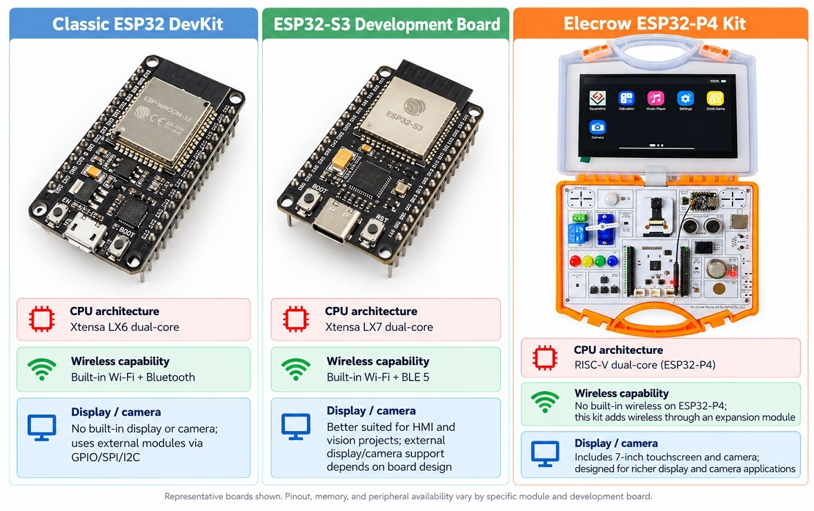
The familiar ESP32 suits connected control projects. The ESP32-S3 adds newer processing features and useful USB capabilities while keeping wireless connectivity on the chip. The ESP32-P4 takes another direction: it concentrates on local processing, graphics, cameras, and wired peripherals.
| Feature | Original ESP32 | ESP32-S3 | ESP32-P4 |
|---|---|---|---|
| Main CPU | Dual-core Xtensa LX6 | Dual-core Xtensa LX7 | Dual-core RISC-V HP system, plus LP RISC-V core |
| Maximum HP clock | 240 MHz | 240 MHz | 360 MHz on v1.x silicon; 400 MHz on v3.x silicon |
| Main on-chip RAM | 520 KB SRAM | 512 KB SRAM | 768 KB HP L2 memory, plus separate LP memory |
| Integrated Wi-Fi | Yes, Wi-Fi 4 | Yes, Wi-Fi 4 | No |
| Integrated Bluetooth | Classic Bluetooth and BLE | BLE | No |
| USB peripheral capability | No native USB OTG | Full-speed USB OTG | High-speed USB OTG |
| Display and camera emphasis | General-purpose peripherals | Parallel display/camera support | MIPI DSI, MIPI CSI, ISP, PPA and video-oriented hardware |
Elecrow specifies a 360 MHz HP processor for this kit. On May 8, 2026, Espressif announced ESP32-P4 chip revision v3.x, which raises the stable maximum clock to 400 MHz. The newer silicon also changes the ESP-IDF requirements, which we cover in the next section.
More important than the raw clock number is the work the chip can offload. The P4 includes an image signal processor (ISP), a pixel-processing accelerator (PPA), JPEG hardware, and an H.264 encoder. These blocks handle parts of camera and graphics processing so the application cores don't have to do every operation in software.
For example, a touchscreen dashboard benefits from dedicated display transfer and pixel handling. A camera application can use the camera interface and image-processing peripherals rather than routing the whole data path through general-purpose GPIO. That architecture, more than the higher CPU frequency, is the reason to consider the P4.
Check the Board Version and Chip Revision Before Loading Examples
Two revision numbers matter on this kit: Elecrow's board version and Espressif's chip revision. Check both before you open the supplied code.
Board version: V1.0 or V1.1
Look for the version marking on the PCB. Elecrow publishes separate course material for V1.0 and V1.1, and the two versions ship with different servos:
| Kit version | Supplied servo type | Relevant course |
|---|---|---|
| V1.0 | 360° continuous-rotation servo | Use the V1.0 Lesson 8 example |
| V1.1 | 180° positional servo | Use the V1.1 Lesson 8 example |
A continuous-rotation servo interprets control pulses as speed and direction commands. A positional servo interprets them as a requested angle. If you run the wrong example, the servo can move in confusing ways even though the PWM signal is valid.
The product that was sent to me is the V1.1 as shown on the lower right of the PCB:
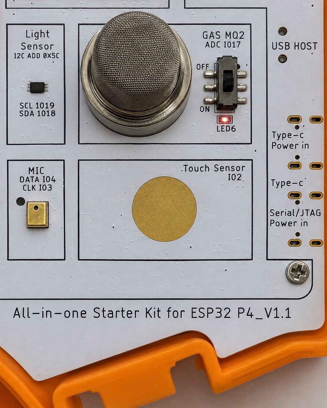
Elecrow's repository currently publishes Eagle schematic files only for V1.0. On a V1.1 board, compare the pin labels against the V1.1 course material and the markings on the PCB.
Chip revision: v1.x or v3.x
Espressif's v3.x chip revision requires ESP-IDF v5.5.3 or later (or v6.0 or later), and you must rebuild firmware for it. Elecrow's setup guide uses ESP-IDF 5.4.2, which only suits v1.x chips.
Check the marking on the ESP32-P4 before you install a toolchain. Espressif adds an X suffix to v3.x part numbers, as in ESP32-P4NRW32X. If the board already runs ESP-IDF firmware, the bootloader also prints the chip revision near the top of the boot log. For a v3.x chip, install ESP-IDF v5.5.3 or later instead of 5.4.2, and expect to adapt Elecrow's examples to any API changes.
First Power-Up: Check the Factory Firmware
Power the kit through USB Type-C with the supplied cable; Elecrow specifies a 5 V input. Use a suitable USB power source or a computer port, and never apply 5 V directly to a GPIO or signal header.
The factory demonstration gives you a useful baseline. If the display, touch input, and other demonstrations work before you change the firmware, you'll have a reference point when something fails later. A feature missing from the factory menu doesn't prove a module is defective, though; the preloaded firmware may not exercise every peripheral.
Elecrow's repository includes factory_firmware and factory_sourcecode folders. Keep a copy of both, along with any flashing instructions, before you flash another application. You don't need to erase the flash first.
On the included OS, here's what I see when I go to settings > about:
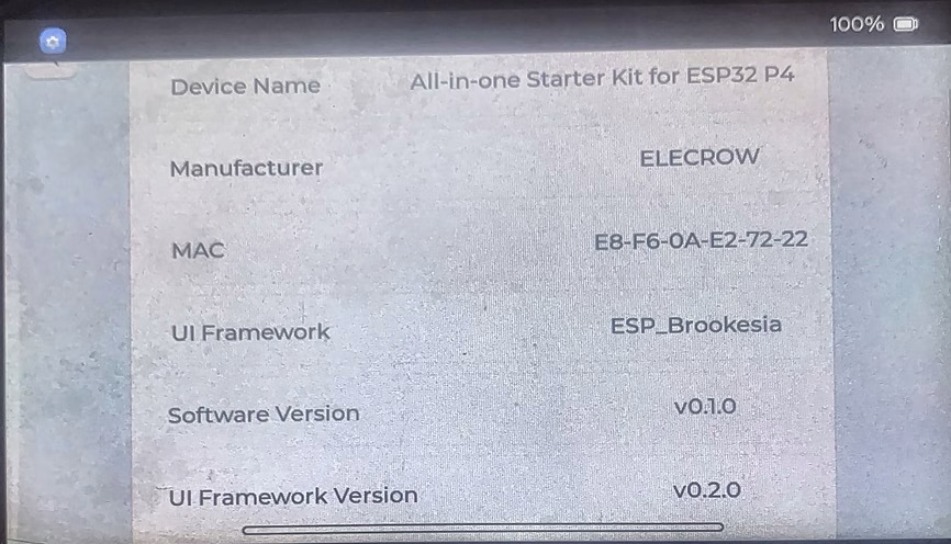
This first check establishes what the hardware does before you make software changes. It isn't meant to prove every module works in one sitting.
Setting Up ESP-IDF for the ESP32-P4
Elecrow provides both Arduino and ESP-IDF learning material. We’ll use ESP-IDF because it gives direct access to the ESP32-P4 target, FreeRTOS, the peripheral drivers, and the configuration options that matter in later display and camera projects. We’ll run one of Elecrow’s lessons first to confirm the toolchain and USB connection, then create our own project.
Step 1: Install VS Code and ESP-IDF
Download Visual Studio Code, open Extensions, and install the Python extension followed by Espressif’s ESP-IDF extension. In the Command Palette, run ESP-IDF: Open ESP-IDF Installation Manager and follow the prompts.
Choose ESP-IDF 5.4.2 for a v1.x chip, the version Elecrow used to configure its lessons. For a v3.x chip, choose v5.5.3 or later. Install to a short path with no spaces, such as C:\esp, because ESP-IDF doesn’t support spaces in its paths or in project paths.
Step 2: Clone Elecrow’s Repository to a Short Path
Elecrow’s lessons nest deeply, and some file paths exceed Windows’ 260-character limit when the repository sits in a long folder. Enable long paths in Git, then clone into a short folder:
git config --global core.longpaths true
cd C:\esp
git clone https://github.com/Elecrow-RD/All-in-one-Starter-Kit-for-ESP32-P4-with-Common-Board-design.git elecrow-p4
Elecrow’s ESP-IDF lessons are in example\V1.0\idf-code and example\V1.1\idf-code, 20 lessons each. The two sets differ only in Lesson 8, the servo lesson.
Step 3: Open a Lesson as a Project
Each lesson folder contains a second folder with the same name, and that inner folder is the ESP-IDF project. In VS Code, choose File > Open Folder and select it:
C:\esp\elecrow-p4\example\V1.1\idf-code\1ESP32P4-dev-kits_gpio\ESP32P4-dev-kits_gpioDon’t change the target. Elecrow includes a ready-made sdkconfig in each lesson that already selects esp32p4 and sets up the PSRAM, flash size, and partition table. Setting the target again regenerates that file and discards those settings.
Step 4: Connect USB1 and Select the Port
The kit has two USB-C ports. Connect the one labelled USB1, which feeds a CH340K USB-to-serial chip wired to the P4’s UART0. The other port, USB2, connects to the P4’s high-speed USB peripheral and isn’t used for flashing.
On Windows, the kit should appear under Device Manager > Ports (COM & LPT) as USB-SERIAL CH340K. If it appears as an unknown device instead, install WCH’s CH340 driver. In the ESP-IDF status bar, select that COM port and set the flash method to UART. The CH340’s control lines put the P4 into download mode automatically, so you don’t need to press any buttons.
Step 5: Build, Flash, and Monitor Lesson 1
Run ESP-IDF: Build your project, then ESP-IDF: Flash your project, then ESP-IDF: Monitor your device. The status bar has buttons for all three. The command-line equivalent in an ESP-IDF terminal is:
idf.py build
idf.py -p COMx flash monitor
Lessons that use the display, sensors, or camera download components from Espressif’s component registry on their first build, so keep the computer online. When Lesson 1 runs, the monitor prints Elecrow’s start-up messages and the green LED next to GPIO5 blinks every 500 ms.
Step 6: Create Your Own Project
With the toolchain and connection confirmed, create a project for our own code. Run ESP-IDF: New Project, set the target to esp32p4, save the project to a short path such as C:\esp\p4-hello, and start from the sample_project template. The template doesn’t enable PSRAM, which the serial and LED programs below don’t need. For display work, start from Elecrow’s lessons, which already have PSRAM configured.
Our First ESP32-P4 Program: Serial Output
Before initializing the 7-inch display, we’ll run a program with as few board-specific dependencies as possible. A counter printed to the serial monitor confirms that a project of our own builds, flashes, and runs. It also gives us somewhere to send diagnostic messages later.
Elecrow’s lessons ship with their own configuration and board drivers. For our code, we’ll start from a clean ESP-IDF project instead.
Create the project
In VS Code, open the Command Palette and run ESP-IDF: New Project. Then:
- Choose the ESP-IDF version you installed earlier.
- Choose the sample_project template from the ESP-IDF list, then click Create Project Using Template sample_project.
- Name the project p4-hello and set the location to C:\esp. Avoid spaces in both, because ESP-IDF doesn’t support them in project paths.
- Set the target to esp32p4. The board setting only matters for hardware debugging, so leave it on the generic ESP32-P4 entry.
- Select the kit’s USB-SERIAL CH340K port.
- Click Create Project, then Open Project.
If you prefer the command line, open an ESP-IDF terminal and run:
cd C:\esp
idf.py create-project p4-hello
cd p4-hello
idf.py set-target esp32p4
The template contains three files:
p4-hello\
├── CMakeLists.txt
└── main\
    ├── CMakeLists.txt
    └── main.c
The top-level CMakeLists.txt marks the folder as an ESP-IDF project. The main folder is the project’s application component, and its CMakeLists.txt registers main.c as a source file. Setting the target also creates sdkconfig, which stores the project’s configuration. Change it through ESP-IDF: SDK Configuration Editor (Menuconfig) rather than editing it by hand.
The default configuration works for this program as-is. It sends console output to UART0, which is the UART that the kit’s CH340K USB-to-serial chip connects to. One exception: if you’re using ESP-IDF 5.5 or later with a v1.x chip, open the configuration editor, search for REV_LESS_V3, enable it, and save. Newer ESP-IDF versions target v3.x chips by default.
Add the code
Open main\main.c and replace its contents with:
#include <stdio.h>
#include "freertos/FreeRTOS.h"
#include "freertos/task.h"

void app_main(void)
{
    unsigned int counter = 0;

    while (1) {
        printf("Hello from ESP32-P4! Count: %u\n", counter++);
        vTaskDelay(pdMS_TO_TICKS(1000));
    }
}
You don’t need to change either CMakeLists.txt file. The template already lists main.c, and every ESP-IDF project includes the components that printf() and the FreeRTOS functions come from.
In ESP-IDF, app_main() is the application’s entry point. There is no Arduino-style setup() and loop() pair to implement. The ESP-IDF runtime initializes the system and then calls app_main() from a FreeRTOS task.
The printf() call sends the counter to the console. pdMS_TO_TICKS(1000) converts 1,000 milliseconds into FreeRTOS ticks, and vTaskDelay() blocks the current task for that many ticks instead of occupying the CPU with a busy-wait loop.
Build, flash, and monitor
Check that the ESP-IDF status bar shows esp32p4 as the target, the CH340K COM port, and UART as the flash method. Then build, flash, and open the monitor. The status bar has buttons for each step, or you can run them from an ESP-IDF terminal:
idf.py -p COMx flash monitorAfter the boot messages, the monitor prints one line about once per second:
Hello from ESP32-P4! Count: 0
Hello from ESP32-P4! Count: 1
Hello from ESP32-P4! Count: 2
Hello from ESP32-P4! Count: 3
Press Ctrl+] to leave the monitor. If flashing reports success but the terminal stays blank, check the selected port and the cable before changing the application code.
Blinking the Onboard LED on GPIO5
Serial output tells us the firmware is running. The next step is to drive a real signal from the P4. Elecrow's first lesson drives LED5 from GPIO5, and its LED circuit sinks current into the pin. That makes the LED active-low: driving GPIO5 low turns the LED on, and driving it high turns it off.
This program toggles the LED with a 500 ms delay between transitions:
#include "freertos/FreeRTOS.h"
#include "freertos/task.h"
#include "driver/gpio.h"
#include "esp_err.h"

#define LED_GPIO GPIO_NUM_5
#define LED_ON 0   /* LED5 is active-low */
#define LED_OFF 1

void app_main(void)
{
    ESP_ERROR_CHECK(gpio_reset_pin(LED_GPIO));
    ESP_ERROR_CHECK(gpio_set_direction(LED_GPIO, GPIO_MODE_OUTPUT));

    while (1) {
        ESP_ERROR_CHECK(gpio_set_level(LED_GPIO, LED_ON));
        vTaskDelay(pdMS_TO_TICKS(500));

        ESP_ERROR_CHECK(gpio_set_level(LED_GPIO, LED_OFF));
        vTaskDelay(pdMS_TO_TICKS(500));
    }
}
The gpio_reset_pin() call returns GPIO5 to its default configuration, and gpio_set_direction() enables output mode. The LED_ON and LED_OFF macros hide the active-low polarity, so the loop reads the way the LED behaves. A full on-off cycle takes about one second.
An ESP-IDF template's main component links every component automatically, so this program builds without changes to the CMake files. If you prefer explicit dependencies, or move the LED code into its own component, declare the GPIO driver in that component's CMakeLists.txt:
idf_component_register(SRCS "main.c"
    INCLUDE_DIRS "."
    REQUIRES esp_driver_gpio)
If serial output works but the LED never changes, confirm that your board version uses GPIO5 for LED5 and check the project's configuration. A failed LED exercise doesn't mean the MCU or the flashing setup is defective.
Exploring the 7-Inch Touchscreen
The serial and LED examples barely exercise the P4's main strengths. The touchscreen is where the chip's dedicated multimedia interfaces start to matter.
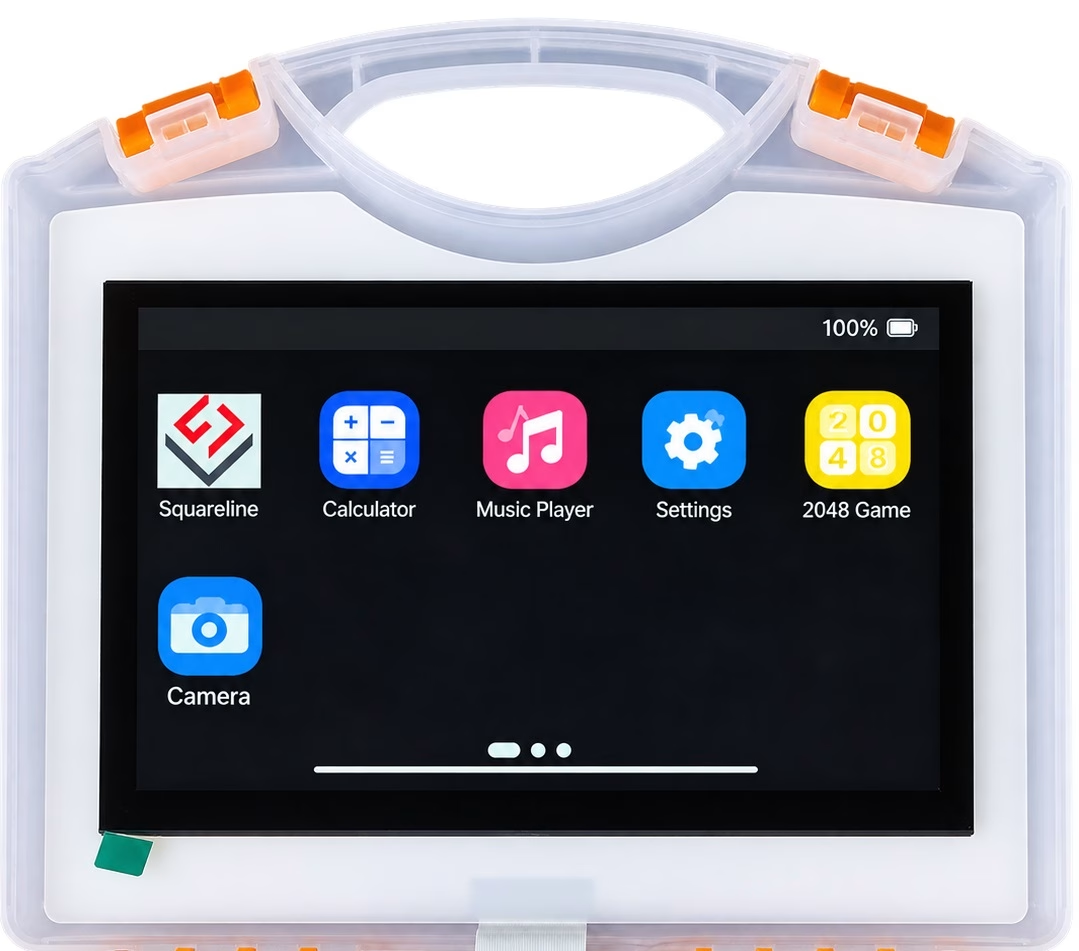
A 1024 × 600 frame contains 614,400 pixels. At 16 bits per pixel, one uncompressed full-screen buffer needs 614,400 × 2 = 1,228,800 bytes, or about 1.17 MiB.
A second full-size buffer doubles that before the application allocates anything else, which is why the display configuration depends on PSRAM. Elecrow's display lesson places LVGL's buffers in PSRAM, and its first lesson enables PSRAM at 200 MHz in sdkconfig (that option appears once you make experimental features visible). The on-chip RAM alone isn't enough for a large graphics application.
Elecrow's display lesson drives the panel over a two-lane MIPI DSI bus with an EK79007 driver IC, and it supplies the board-specific setup for that combination. Start with Elecrow's example for your board version rather than writing your own initialization sequence. Use this order:
- Open Elecrow's ESP-IDF course for your V1.0 or V1.1 kit.
- Find the LCD project and read its component requirements before building.
- Check the project's ESP-IDF version and its display and touch driver dependencies.
- Build and flash the unchanged demonstration first.
- Record whether the display renders correctly and whether touch coordinates respond as expected.
Elecrow's repository lists LVGL 8.3.3 as a dependency. LVGL is a practical next step for dashboards, menus, and interactive controls, but examples that depend on different major LVGL versions can produce API or build errors when mixed.
Running the supplied display example unchanged establishes a working hardware and driver combination before you start modifying the graphics code.
Wireless Connectivity and ESP32-C6 Expansion
Unlike the original ESP32 or the ESP32-S3, the ESP32-P4 has no Wi-Fi or Bluetooth radio of its own. A P4 application that needs wireless networking has to use another device to provide it.
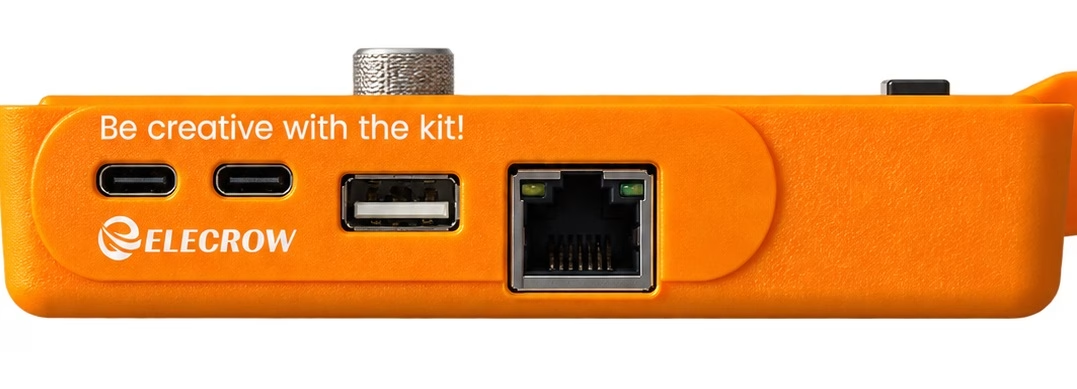
Elecrow sells plug-in wireless modules for this slot, including an ESP32-C6 version. The module exposes UART transmit and receive pins along with a few GPIOs, so the P4 talks to it over a serial link: the C6 runs the radio, and the P4 handles the user interface, sensors, and application logic. Both chips need matching firmware, so plugging in the module doesn't enable networking by itself.
For a wired connection, the kit has a 100 Mbps Ethernet port. Ethernet suits an HMI panel that stays in one installation and benefits from a predictable network connection.
ESP32-C6 networking deserves its own interface description, driver setup, and connectivity test, so we'll cover it in a separate tutorial. The initial setup in this article doesn't need a wireless module.
Troubleshooting the ESP32-P4 Starter Kit
Most first-day problems with this kit come down to the cable, the toolchain version, or a board setting. Start with these checks.
The Computer Powers the Kit but Doesn’t Detect It
Check the USB cable and the USB-C port first. A charge-only cable can supply 5 V without carrying data. Try a known data-capable cable and check Device Manager for a new COM port.
ESP-IDF Doesn’t Recognize the esp32p4 Target
Check which ESP-IDF installation the terminal or VS Code extension is using. A toolchain set up for another chip family, or an older framework without P4 support, won't accept the target. For Elecrow's examples on a v1.x chip, use ESP-IDF 5.4.2.
New Firmware Flashes but Won’t Boot
Check the chip revision. A v3.x chip needs ESP-IDF v5.5.3 or later and firmware rebuilt for that revision; firmware from ESP-IDF 5.4.2 doesn't support it.
Flashing Fails Even Though a Port Appears
Close other serial-monitor programs, verify the port selection, and retry. If automatic bootloader entry isn't working, follow the kit's download-mode procedure. A flashing failure is a separate problem from a compilation error, so read the last meaningful message in the build or flashing log before making changes.
The Serial Monitor Is Blank
A successful build doesn't guarantee that the firmware prints to the port you're monitoring. Check the project's console configuration, the selected port, the cable, and the reset behavior. Early boot messages tell you whether you're connected to the right channel.
The LED Doesn’t Blink
Confirm GPIO5 for your board version. Remember that LED5 is active-low, so it lights when GPIO5 is low. If the serial counter still runs, the problem more likely concerns the pin, its configuration, or the LED circuit than basic CPU execution.
The Touch or Hall Sensor Doesn’t Respond
Check the selector switch next to the wireless-module slot. Both sensors need it in the Hall/touch position.
The Display Goes Blank After the First Program
The serial and blink programs don't initialize the panel or touch controller, so a blank display after flashing them is expected. Load Elecrow's display example when you want to use the screen again.
The Servo Moves Continuously Instead of Holding an Angle
Check the board version. V1.0 kits ship with a continuous-rotation servo and V1.1 kits with a 180° positional servo. Use the matching Lesson 8 example before adjusting pulse widths.
Is the Elecrow ESP32-P4 Starter Kit Worth It?
The main advantage of the SEE00804D is convenience. Elecrow assembles the touchscreen, camera, audio hardware, and common sensor board for you. That suits a classroom, or a developer who wants to work on firmware and interface design without first wiring several peripherals.
There are tradeoffs. The P4 isn't the easiest choice if all you need is Wi-Fi and a few sensor inputs; a conventional ESP32 or ESP32-S3 may be simpler and less expensive. Wireless expansion takes extra hardware and firmware on a second chip. The fixed circuitry also gives you less freedom to move a sensor to another GPIO than a set of separate modules would.
The development environment is another consideration. A serial-output program is approachable, but graphics, cameras, PSRAM configuration, and multiple drivers take more work than the usual Arduino blink sketch. Elecrow's examples give you a starting point for that more advanced software.
We'd choose this kit for exploring touch interfaces, camera handling, and P4-specific peripherals. For a basic wireless temperature logger or relay controller, we'd choose a simpler board. The kit earns its price when you plan to use the display and multimedia features rather than treating them as extras.
Conclusion
The ESP32-P4 isn't a replacement for every ESP32 board. It's a different kind of microcontroller, intended for applications where local processing and rich interfaces matter more than an integrated radio.
Elecrow's starter kit gives you a practical way to learn that architecture. Start by identifying the board version and chip revision and saving the factory resources. Then set up the matching ESP-IDF version and confirm serial output and GPIO control. Once those basics work, run the display example before changing its drivers or writing a custom LVGL interface.
Future tutorials will explore the individual sensors, camera processing, and wireless expansion. The important first step is a development setup whose behavior you can reproduce and troubleshoot.
References
- Elecrow: All-in-One Starter Kit for ESP32-P4 (SEE00804D)
- Elecrow Wiki: Setup instructions and V1.0/V1.1 courses
- Elecrow: All-in-One Starter Kit for ESP32-P4 ESP-IDF user manual (PDF)
- Elecrow GitHub: Examples, pin definitions, and factory firmware
- Elecrow: Wireless module for CrowPanel Advanced series
- Espressif: ESP32-P4 SoC overview
- Espressif: ESP32-P4 v3.x upgrade announcement (May 2026)
- Espressif: ESP32-P4 Chip Revision v3.x User Guide
- Espressif: ESP-IDF GPIO driver reference for ESP32-P4
- CNX Software: ESP32-P4 learning and prototyping kit specifications