Suppose you want an Arduino Uno and an ESP32 to talk to each other. Both boards have digital input and output pins, and both support familiar protocols such as UART, SPI, and I2C. Connecting them should be straightforward, right?
There's one important difference: the Arduino Uno R3 uses 5V logic, while the ESP32 uses 3.3V logic. Connect a 5V signal directly to an ESP32 GPIO pin, and you risk damaging the microcontroller. Go the other way, though, and a 3.3V signal might work perfectly well with the 5V Arduino.
Why is that?
The answer lies in logic voltage thresholds, which determine how a microcontroller interprets a digital signal. In this tutorial, we'll look at how 3.3V and 5V logic work and when you can connect devices directly. We'll also cover when you need a voltage divider, a buffer, or a logic level translator. Then we'll wire a simple circuit that lets a 5V Arduino Uno safely send digital signals to an ESP32.
What Are Logic Levels?
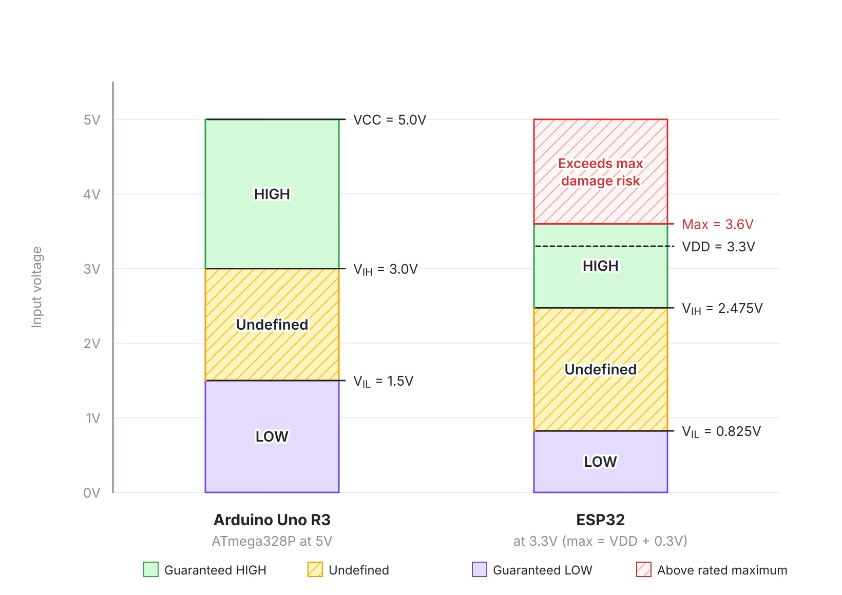
Microcontrollers communicate using binary signals: a digital pin represents either logic LOW (0) or logic HIGH (1). Ideally, LOW sits at 0V and HIGH sits at the logic supply voltage: about 5V in a 5V system or 3.3V in a 3.3V system.
In practice, a digital input doesn't need an exact voltage to recognize either state. The 5V Arduino Uno R3, for example, accepts voltages well below 5V as a valid HIGH. Likewise, a LOW doesn't have to be exactly 0V. Every digital input has two specifications that define these ranges:
- VIH (Input HIGH Voltage): The minimum input voltage guaranteed to register as HIGH.
- VIL (Input LOW Voltage): The maximum input voltage guaranteed to register as LOW.
Any voltage between these two limits falls into an undefined region. The microcontroller might read it as HIGH or LOW, and the result can change from one moment to the next. A signal that lingers there can also make a CMOS input draw extra current, because both transistors in its input stage partly conduct.
Some inputs, including the ATmega328P's standard I/O pins, pass the signal through a Schmitt trigger. A Schmitt trigger adds hysteresis: its rising threshold sits slightly above its falling threshold. As a result, small amounts of noise on a slow edge don't make the input toggle repeatedly.
Inputs are only half the story, though. Every digital output also has two specifications:
- VOH (Output HIGH Voltage): The minimum voltage the output guarantees when driving HIGH.
- VOL (Output LOW Voltage): The maximum voltage the output guarantees when driving LOW.
A connection works reliably when the sender's output levels land inside the receiver's guaranteed input ranges. The gap between them is called the noise margin, and each logic state has one:


A positive noise margin means the receiver should read the signal correctly, with some room left over for noise. A negative margin means the datasheets don't guarantee the connection, even if it seems to work on your bench.
Logic Voltage Thresholds of Arduino Uno and ESP32
To make these numbers concrete, let's compare the ATmega328P used by the Arduino Uno R3 with the ESP32. The table below lists the key parameters for each chip at its nominal supply voltage.
| Parameter | Arduino Uno R3 (ATmega328P at 5V) | ESP32 (at 3.3V) |
|---|---|---|
| Logic supply voltage | 5V | 3.3V |
| Minimum input HIGH (VIH) | 0.6 × VCC = 3.0V | 0.75 × VDD = 2.475V |
| Maximum input LOW (VIL) | 0.3 × VCC = 1.5V | 0.25 × VDD = 0.825V |
| Minimum output HIGH (VOH) | 4.2V while sourcing 20 mA | 0.8 × VDD = 2.64V while sourcing up to 40 mA |
| Maximum output LOW (VOL) | 0.9V while sinking 20 mA | 0.1 × VDD = 0.33V |
| Maximum voltage on a GPIO pin | VCC + 0.5V = 5.5V | VDD + 0.3V = 3.6V |
| Accepts a direct 5V input? | Yes, within its rated conditions | No |
Note that the output values include test currents. Most logic connections draw far less current than these test conditions, so a real output typically sits much closer to its supply rail or ground. These values also apply only to these two microcontrollers. Other Arduino boards, ESP32 variants, and external devices may have different specifications.
Now look at the Arduino's 3.0V HIGH threshold. A 3.3V signal clears it, which explains why many 3.3V sensors work directly with 5V Arduino boards. We'll come back to why that isn't the whole story, but first, let's look at the more dangerous direction.
Can You Connect a 5V Signal Directly to a 3.3V Microcontroller?
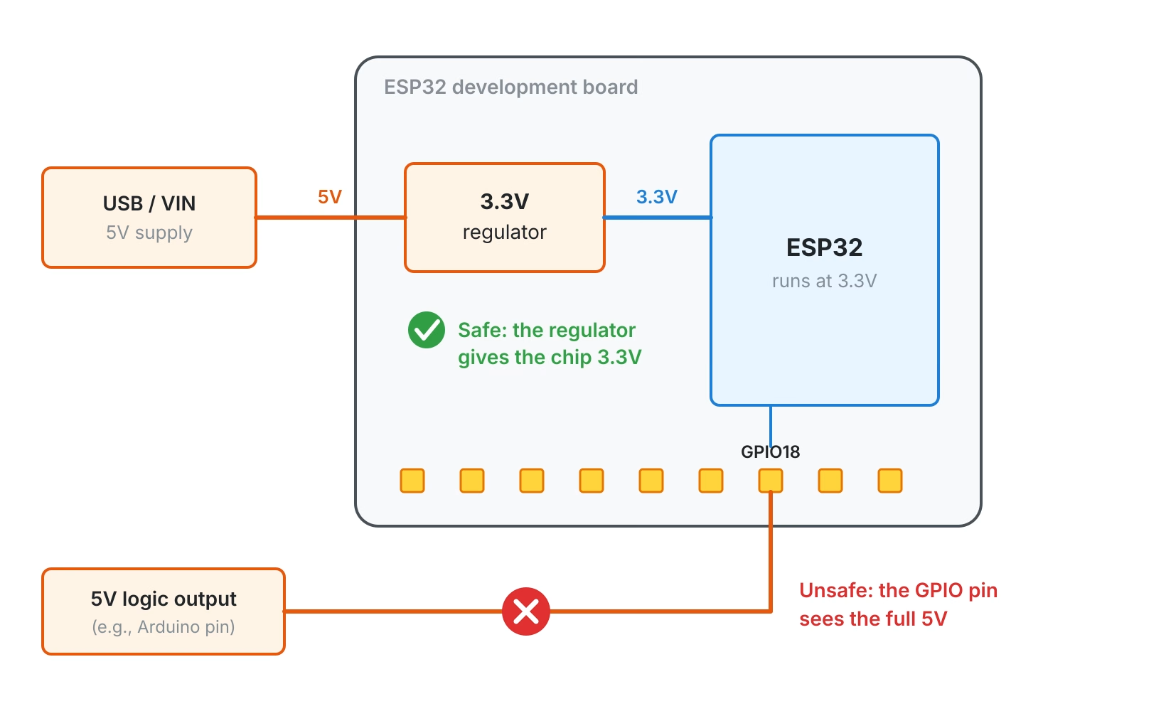
For an ESP32, the answer is no. Its GPIO pins aren't 5V tolerant. Espressif limits input-pin voltage to VDD + 0.3V, which is 3.6V on a 3.3V supply.
That ceiling moves with the supply voltage. Espressif allows VDD anywhere from 3.0V to 3.6V, so on a board whose regulator runs at 3.0V, the limit drops to 3.3V. A 5V signal exceeds the limit anywhere in that range.
A common mistake is assuming the ESP32 can tolerate 5V because its development board has a 5V or VIN power input. But a power input and a GPIO pin are different things. Many ESP32 development boards include a voltage regulator that converts the external supply down to 3.3V for the microcontroller. That regulator protects the chip's supply, not its GPIO pins.
What Happens Inside the Pin?
Like most CMOS chips, the ESP32 protects its pins against electrostatic discharge (ESD). These protection structures typically behave like two diodes per pin. One runs from the pin up to the 3.3V supply rail, and the other runs from ground up to the pin.
During normal operation, both diodes stay reverse-biased and carry no current. Apply 5V to the pin, though, and the upper diode turns on once the pin rises about 0.6V above the rail. Current then flows from the 5V source into the chip's 3.3V supply:
With a direct wire, only the resistance of the source and wiring limits this current, so it can be large. Excess current can damage the diode or the pin. It can also lift the 3.3V rail, because most voltage regulators can source current but can't sink it. In the worst case, injected current can trigger latch-up, a parasitic short between the supply and ground that can destroy the chip.
Even if an ESP32 appears to work after receiving a 5V signal, that doesn't make the connection safe. Damage can build up gradually, and erratic behavior may only appear later. The same caution applies to other 3.3V microcontrollers, although individual tolerances vary.
Do You Need a Level Shifter for 3.3V to 5V Signals?
In the other direction, the answer is often no, but it's worth checking. A 3.3V output can't push a 5V input beyond its rating, so safety isn't the concern. The question is whether the receiver will reliably read the signal as HIGH.
This is where noise margins come in. For an ESP32 output driving an Arduino Uno input, the datasheet values give:


The LOW side has plenty of room. The HIGH side has a negative margin, so the datasheets don't guarantee that the Arduino will read the ESP32's HIGH.
That 2.64V minimum assumes the pin sources up to 40 mA, however. A logic input draws almost no current, so in practice, the ESP32's output usually sits close to 3.3V. That's why the link typically works on the bench.
Even then, a margin of about 0.3V is thin for a permanent design. A buffer that drives a full 5V removes the doubt, as we'll see in Method 3.
TTL vs. CMOS Input Levels
Not every 5V input uses the same thresholds, so the answer also depends on the receiving device. Older TTL logic, and modern parts with TTL-compatible inputs, recognize anything above 2.0V as HIGH and anything below 0.8V as LOW. A 3.3V output clears those levels easily.
Many 5V CMOS parts, on the other hand, scale their thresholds with the supply. A typical 5V CMOS input needs 0.7 × VCC, or 3.5V, to register a HIGH, which a 3.3V output can't reach. The ATmega328P sits between the two, at 0.6 × VCC.
Part names often hint at the input type. In the 74-series logic families, a "T" in the family name, as in HCT or AHCT, usually marks TTL-compatible inputs. When the receiver needs more than a 3.3V output can deliver, use a translator that actively drives the signal up to 5V.
Fortunately, there are several ways to connect different logic voltages safely, in either direction. We'll start with one-directional methods and then move on to bidirectional ones.
Method 1: Using a Resistor Voltage Divider
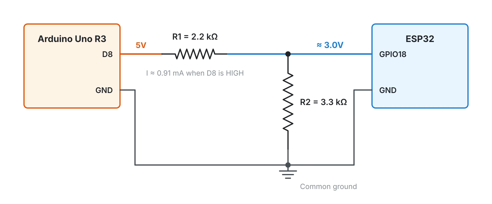
To send a signal from a 5V output to a 3.3V input, a resistor voltage divider is one of the simplest solutions. Two resistors in series split the input voltage, and the receiver reads the voltage at their junction:
The voltage at the junction between R1 and R2 is:

We don't need exactly 3.3V. A target of about 3.0V sits between the ESP32's 2.475V HIGH threshold and its 3.6V limit. A 2.2 kΩ and 3.3 kΩ pair gets us there:
- R1 = 2.2 kΩ
- R2 = 3.3 kΩ
- Vin = 5V

When the Arduino output goes LOW, the divider output also falls to about 0V. With the output HIGH, the divider draws about 0.91 mA, a trivial load for an Arduino pin.
Checking the Worst Case
The 3.0V result assumes a perfect 5V supply and perfect resistors. Real parts vary, so it's worth checking how low and how high the junction voltage can go. Two variations matter most:
- Resistor tolerance: Common 5% resistors can sit anywhere within ±5% of their marked value.
- Supply voltage: USB ports typically supply 4.75V to 5.25V, and the Uno's input protection drops a little more. On a weak port or a long cable, the Uno's 5V rail can sag to around 4.5V.
The low corner pairs the lowest supply with R1 at its highest value and R2 at its lowest. The high corner does the opposite:
| Case | Supply | R1 | R2 | Junction voltage |
|---|---|---|---|---|
| Nominal | 5.0V | 2.2 kΩ | 3.3 kΩ | 3.00V |
| Low corner, 5% resistors | 4.5V | 2.31 kΩ | 3.135 kΩ | 2.59V |
| High corner, 5% resistors | 5.25V | 2.09 kΩ | 3.465 kΩ | 3.27V |
| Low corner, 1% resistors | 4.5V | 2.222 kΩ | 3.267 kΩ | 2.68V |
| High corner, 1% resistors | 5.25V | 2.178 kΩ | 3.333 kΩ | 3.18V |
With 5% resistors, the low corner clears the ESP32's 2.475V threshold by only about 0.12V. That margin also assumes the ESP32 runs at exactly 3.3V. If its rail runs at 3.6V instead, VIH rises to 2.7V, and the 5% low corner falls short.
Switching to 1% resistors widens the low-corner margin to about 0.2V at a 3.3V ESP32 supply. Both high corners also stay below 3.3V, so they remain within the ESP32's input limit even if its supply runs as low as 3.0V.
When Is a Voltage Divider Appropriate?
A divider works well for slow, one-directional digital signals, such as a status line, a button-state output, or a UART transmit line.
Its speed limit comes from capacitance. The ESP32's input pin, the breadboard, and the wiring all add capacitance at the junction. From the input's point of view, the divider acts like a single resistor equal to R1 and R2 in parallel, called the Thevenin resistance:

That resistance and the junction capacitance form an RC circuit. Assuming about 15 pF of combined pin and breadboard capacitance, the time constant is:

The 10%-to-90% rise time is about 2.2 time constants, or roughly 44 ns. For comparison, one bit at 115200 baud lasts about 8.7 µs, so the edges barely register. At a 10 MHz SPI clock, though, each half-cycle lasts only 50 ns, and the slow edge would consume most of it.
The resistor values set the trade-off. Smaller resistors give faster edges but draw more current from the 5V output. Larger ones, such as 22 kΩ and 33 kΩ, save current but make the edges ten times slower.
A divider also can't raise a 3.3V signal to 5V; it can only reduce voltage. For faster signals, or for the opposite direction, you'll need an active circuit.
Method 2: Using a 5V-Tolerant Buffer (5V to 3.3V)
When a 5V signal switches too fast for a divider, a logic buffer powered from 3.3V can take its place. Some 3.3V logic families have 5V-tolerant inputs, which accept up to 5.5V even when the chip runs from 3.3V. The 74LVC125A quad buffer, available from manufacturers including Texas Instruments and Nexperia, is a common example.
The buffer's inputs read the 5V signal, and its push-pull outputs drive a clean 0V-to-3.3V signal into the ESP32. Unlike a divider, the buffer doesn't rely on resistors to set its output level, so its edges stay sharp at much higher speeds. Like the divider, though, it only works in one direction, from 5V down to 3.3V.
Method 3: Using a 5V Logic Buffer (3.3V to 5V)
Method 3 mirrors Method 2. When a 5V device needs a full 5V HIGH from a 3.3V source, a buffer powered from 5V does the job. The 74AHCT125, for example, has TTL-compatible inputs that recognize 2V as HIGH, yet its outputs swing up to its 5V supply.
It also works in only one direction, from 3.3V to 5V, but it's simple, fast, and inexpensive. Many makers use it to drive 5V peripherals, such as addressable LED strips, from 3.3V microcontrollers.
Together, Methods 2 and 3 handle both directions with push-pull buffers, as long as each signal travels only one way. Bidirectional signals need a different approach.
Method 4: Using a MOSFET Logic Level Shifter
When a single line carries data in both directions, none of the methods so far will do. One of the most common solutions is a small module based on BSS138 N-channel MOSFETs. It translates signals either way without a direction-control pin.
How the BSS138 Circuit Works
Each channel uses one MOSFET and two pull-up resistors, one on each side. The MOSFET's gate connects to the low-voltage supply, its source to the low-voltage signal, and its drain to the high-voltage signal.
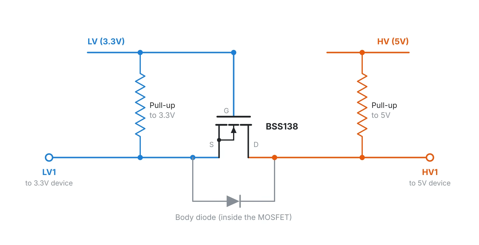
The circuit has three states:
- Neither side pulls LOW: The source sits at 3.3V, the same as the gate, so the MOSFET stays off. Each pull-up holds its own side at its own rail: 3.3V on the low side and 5V on the high side.
- The low-voltage device pulls LOW: The source drops to 0V, giving a 3.3V gate-source voltage. The MOSFET turns on and pulls the high-voltage side LOW too.
- The high-voltage device pulls LOW: The MOSFET's internal body diode conducts first, pulling the source down to about 0.6V. That raises the gate-source voltage enough to turn the MOSFET fully on, and the low side follows to near 0V.
When the device releases the line, the pull-ups bring both sides back to their rails, and the MOSFET switches off again. Because the circuit only ever pulls lines LOW, it particularly suits open-drain buses such as I2C.
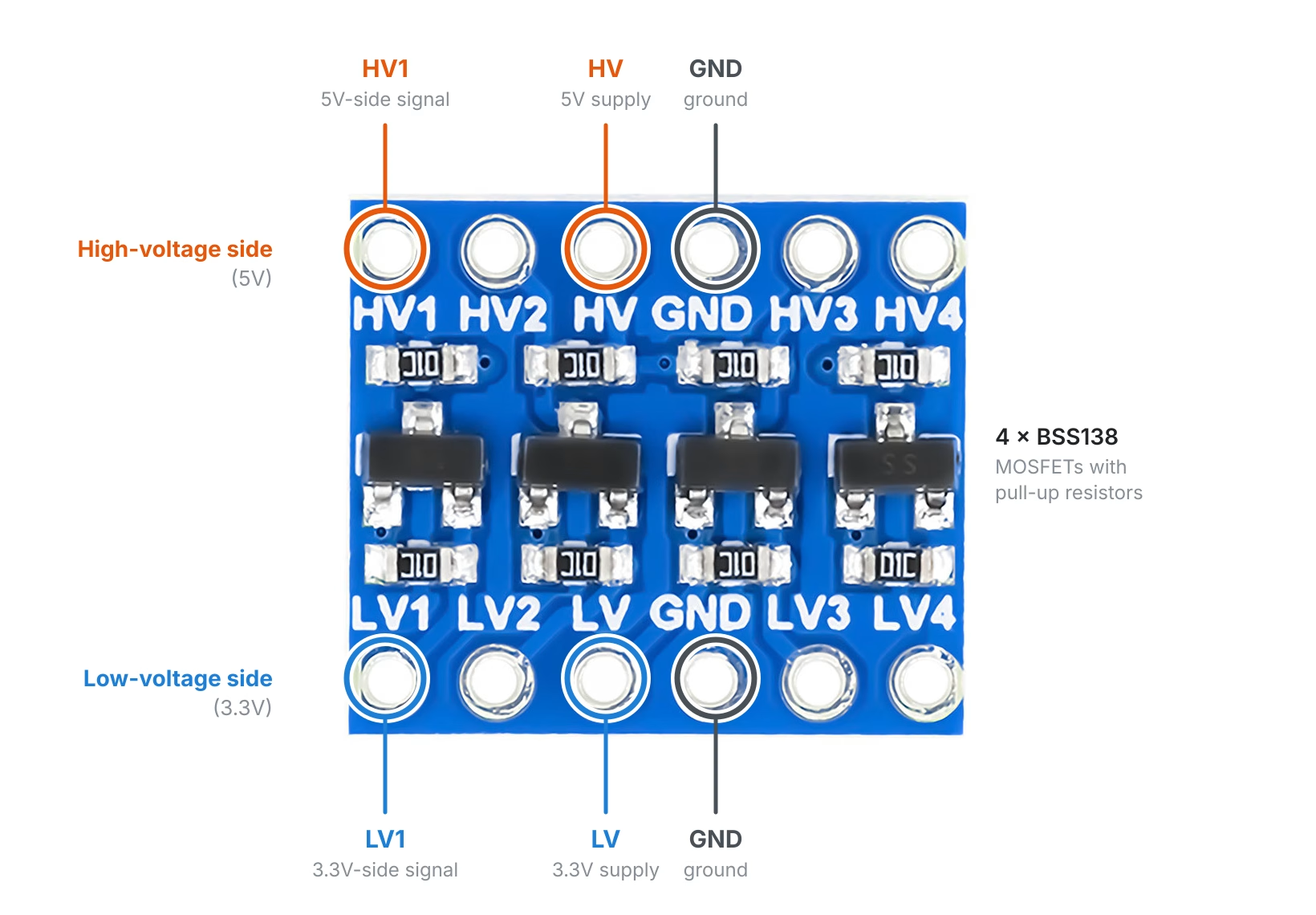
These modules typically have four channels, with connections labeled:
- HV: Higher-voltage supply, commonly 5V
- LV: Lower-voltage supply, commonly 3.3V
- GND: Common ground
- HV1–HV4: High-voltage signal connections
- LV1–LV4: Low-voltage signal connections
Speed Limits of the BSS138 Module
The BSS138 module isn’t a universal solution, though. Every rising edge comes from a pull-up resistor charging the line’s capacitance, and many of these modules use 10 kΩ pull-ups. On the module pictured earlier, for example, the resistors carry the marking “01C”, the EIA-96 code for 10.0 kΩ. The I2C specification measures rise time between 30% and 70% of the supply voltage:

With 10 kΩ pull-ups and a 50 pF bus, the rise time is about 424 ns. That fits within I2C Standard-mode's 1000 ns limit at 100 kHz. However, it exceeds Fast-mode's 300 ns limit at 400 kHz, so Fast-mode buses may need stronger, lower-value pull-ups.
Pull-ups also combine in parallel. If a sensor module already has its own 10 kΩ pull-ups, the effective resistance on that side drops to 5 kΩ. Stronger pull-ups speed up the edges, but they also increase the current each device must sink to pull the line LOW.
The same pull-up dependence makes the module a poor fit for fast push-pull signals, such as SPI clocks. A push-pull driver on the low side pulls the high side LOW through the MOSFET quickly. Its rising edge, however, still depends on the slow pull-up.
Method 5: Using a Dedicated Logic Level Translator IC
Where signal timing and reliability matter, a dedicated translator IC is often the better choice. The right part depends on the type of signal:
- TXS0108E (Texas Instruments): An eight-channel, auto-direction translator that supports both open-drain and push-pull signals within its specified operating conditions.
- PCA9306 (Texas Instruments): Designed specifically for bidirectional I2C and SMBus translation.
- SN74LVC8T245 (Texas Instruments): An eight-bit, dual-supply translator for push-pull signals. A single direction-control (DIR) pin sets all eight channels at once.
- SN74LVC1T45 (Texas Instruments): A single-bit, dual-supply translator with its own DIR pin, useful for a lone signal that travels the other way.
Choose a translator based on the signal type, not because a module is advertised as "3.3V to 5V compatible." A translator designed for I2C might not work reliably on a fast SPI bus, even though both carry the same HIGH and LOW levels.
Practical Notes on TXS0108E Modules
TXS0108E breakout boards are popular, but they come with a few requirements that often catch first-time users:
- Supply order: VCCA, the A-side supply, must not exceed VCCB, and it must not exceed 3.6V. Connect 3.3V to VCCA and 5V to VCCB, not the other way around.
- Output enable: The OE pin uses VCCA as its reference, and pulling it LOW puts every output in a high-impedance state. Drive OE HIGH, to 3.3V, to enable translation, and check whether your module already pulls it up or down.
- Look-alike parts: TXB0108 modules look almost identical but are intended for push-pull signals. They generally don't work reliably with I2C pull-up resistors.
- Loading: The TXS0108E uses edge accelerators that briefly boost each transition. Heavy capacitive loads or strong external pull-ups can confuse them, so keep the wiring short.
Practical Example: Sending a 5V Arduino Signal to an ESP32
Let's put the voltage divider to use. We'll connect an Arduino Uno R3 to an ESP32 development board. The Arduino will toggle a digital output every 500 milliseconds, and the ESP32 will read that signal.
Components Needed
- Arduino Uno R3
- ESP32 development board
- 2.2 kΩ resistor (1% tolerance recommended)
- 3.3 kΩ resistor (1% tolerance recommended)
- Breadboard
- Jumper wires
- USB cables
- Multimeter (recommended)
- Optional, for the return path: 74AHCT125 buffer, 0.1 µF capacitor, and 10 kΩ resistor
Choosing the Pins
We'll use digital pin 8 on the Arduino and GPIO18 on the ESP32. GPIO18 is a general-purpose pin with no special role during boot, which makes it a safe choice. When you adapt this circuit, avoid these ESP32 pins:
- Strapping pins (GPIO0, GPIO2, GPIO5, GPIO12, and GPIO15): The ESP32 samples these pins at reset to choose its boot mode and settings, so an external signal can change those settings. For example, a HIGH on GPIO12 at boot selects a 1.8V flash supply. That setting stops modules with 3.3V flash, such as the ESP32-WROOM-32, from booting.
- GPIO6 to GPIO11: On most modules, these pins connect to the internal SPI flash.
Wiring Diagram
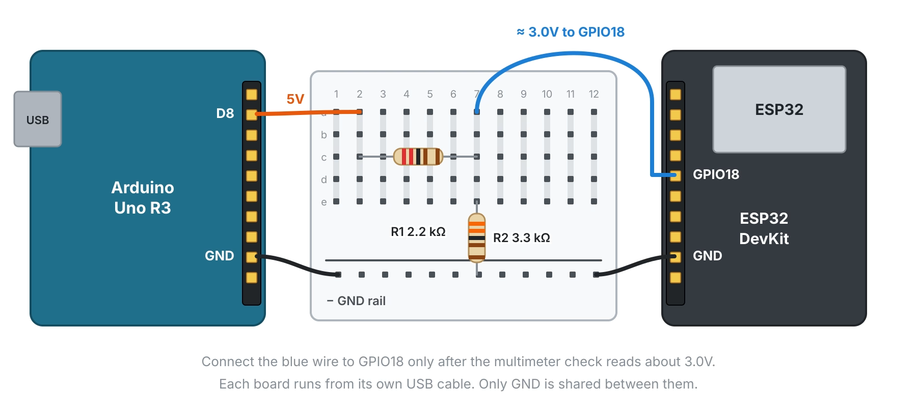
Wire the divider between the two boards as follows:
| Arduino / Circuit | Connection |
|---|---|
| Arduino D8 | R1 (2.2 kΩ) |
| Other end of R1 | ESP32 GPIO18 and one end of R2 |
| Other end of R2 (3.3 kΩ) | GND |
| Arduino GND | ESP32 GND |
The Arduino and ESP32 must share a common ground so they have the same voltage reference. Power each board through its own USB port, and don't connect their 5V and 3.3V rails together.
R2 also does a second job. While the Uno resets, its pins switch to high-impedance inputs, so D8 stops driving the divider. R2 then pulls GPIO18 to GND, and the ESP32 reads a clean LOW instead of a floating input.
Wire everything except the connection to GPIO18 for now. We'll check the divider output before it reaches the ESP32.
Arduino Code
Upload the following sketch to the Arduino Uno:
const int signalPin = 8;

void setup() {
  pinMode(signalPin, OUTPUT);
  digitalWrite(signalPin, LOW);
}

void loop() {
  digitalWrite(signalPin, HIGH);
  delay(500);

  digitalWrite(signalPin, LOW);
  delay(500);
}
Inside setup(), we configure pin 8 as an output. Then loop() alternates it between HIGH and LOW at half-second intervals.
When HIGH, D8 outputs close to 5V, and the divider delivers about 3.0V. When LOW, both sides measure close to 0V.
Checking the Divider with a Multimeter
Before connecting the divider to GPIO18, confirm its output voltage with a multimeter. A quick measurement catches wiring mistakes before 5V reaches the ESP32.
A toggling signal is hard to read on a multimeter, so first upload this short test sketch, which holds D8 HIGH:
void setup() {
  pinMode(8, OUTPUT);
  digitalWrite(8, HIGH);
}

void loop() {
}
Then measure between the junction of R1 and R2 and GND. The reading tells you whether the wiring is correct:
| Reading at the junction | Likely cause |
|---|---|
| About 3.0V | Correct wiring |
| About 5V | R2 isn't reaching GND |
| About 2.0V | R1 and R2 are swapped |
| About 0V | R1 isn't connected, or D8 isn't HIGH |
Once the reading is correct, re-upload the toggling sketch and connect the junction to GPIO18.
ESP32 Code
Next, upload this sketch to the ESP32 using the Arduino IDE. If you haven't set up the IDE for the ESP32 yet, install the "esp32" board package by Espressif through the Boards Manager. Then select your board; "ESP32 Dev Module" works for most DevKitC-style boards.
const int inputPin = 18;
int previousState = -1;

void setup() {
  Serial.begin(115200);
  pinMode(inputPin, INPUT);
}

void loop() {
  int currentState = digitalRead(inputPin);

  if (currentState != previousState) {
    Serial.print("Signal: ");

    if (currentState == HIGH) {
      Serial.println("HIGH");
    } else {
      Serial.println("LOW");
    }

    previousState = currentState;
  }

  delay(10);
}
Here, digitalRead() checks the voltage level at GPIO18 and returns HIGH or LOW. The sketch prints a message only when the input changes state, which makes the transitions easy to follow. The pin uses plain INPUT mode because R2 already acts as a pull-down.
With both boards running, open the Serial Monitor at 115200 baud. It should show:
Signal: HIGH
Signal: LOW
Signal: HIGH
Signal: LOW
The first line depends on which state the signal is in when the ESP32 starts.
Viewing the Signal on an Oscilloscope
If you have an oscilloscope, compare the waveforms before and after the divider. At this slow toggle rate, the two waveforms look nearly identical apart from their amplitudes. Zoom into a rising edge, though, and you can see the RC effect described in Method 1.
Keep in mind that the scope probe adds its own capacitance, typically around 10 pF for a 10× probe. The measured edge will therefore look slightly slower than the edge the ESP32 sees without the probe.
Going Further: Sending a Signal Back to the Arduino
So far, the example covers only the 5V-to-3.3V direction. To send a signal back, you could rely on the ESP32's output clearing the Uno's 3.0V threshold. For a guaranteed connection, though, add a 74AHCT125 buffer from Method 3 to the same breadboard:
| 74AHCT125 Pin | Connection |
|---|---|
| VCC (pin 14) | Arduino 5V |
| GND (pin 7) | Common GND |
| 1OE (pin 1) | GND, which enables buffer 1 |
| 1A (pin 2) | ESP32 GPIO19, plus a 10 kΩ resistor to GND |
| 1Y (pin 3) | Arduino D7 |
| 2OE, 3OE, 4OE (pins 4, 10, 13) | Arduino 5V, which disables the unused buffers |
| 2A, 3A, 4A (pins 5, 9, 12) | GND |
| 0.1 µF capacitor | Between pin 14 and pin 7, close to the chip |
The 10 kΩ resistor holds the buffer's input LOW while the ESP32 boots and GPIO19 floats.
Upload this sketch to the ESP32 to toggle GPIO19:
const int outputPin = 19;

void setup() {
  pinMode(outputPin, OUTPUT);
}

void loop() {
  digitalWrite(outputPin, HIGH);
  delay(500);

  digitalWrite(outputPin, LOW);
  delay(500);
}
Then upload this sketch to the Arduino to read D7:
const int inputPin = 7;
int previousState = -1;

void setup() {
  Serial.begin(9600);
  pinMode(inputPin, INPUT);
}

void loop() {
  int currentState = digitalRead(inputPin);

  if (currentState != previousState) {
    Serial.print("Signal: ");

    if (currentState == HIGH) {
      Serial.println("HIGH");
    } else {
      Serial.println("LOW");
    }

    previousState = currentState;
  }

  delay(10);
}
Open the Serial Monitor at 9600 baud, and you should see the same alternating HIGH and LOW messages. This time, the buffer drives D7 with a full 5V HIGH, so the connection no longer depends on the ESP32's output voltage.
Logic Level Shifting for UART, I2C, and SPI
So far, we've looked at single digital signals. The same principles apply to communication buses, but the right circuit depends on how each interface drives its lines.
UART: Consider Each Direction Separately
UART uses two signal lines, TX and RX, with each device's TX connected to the other's RX. Between an Arduino Uno R3 and an ESP32, that gives two paths with different needs:
The Arduino-to-ESP32 path always needs level shifting. The ESP32-to-Arduino path often works directly, subject to the noise-margin caveat above.
For the Arduino TX line, the rise-time estimate from Method 1 shows that a divider handles 115200 baud comfortably. At higher baud rates, or with long wires in a noisy environment, a buffer or translator becomes more important.
I2C: Watch the Pull-Up Resistors
I2C works differently. Its SDA and SCL lines are open-drain: devices pull the lines LOW, and pull-up resistors bring them HIGH. That makes the pull-up voltage critical.
Imagine connecting a 3.3V ESP32 to a sensor module powered by 5V. If the module's onboard pull-ups connect to 5V, SDA and SCL idle at 5V. That voltage reaches the ESP32's pins before any data is exchanged.
A bidirectional I2C translator, such as a BSS138 module or a PCA9306-based circuit, separates the two voltage domains. Its low-voltage side uses pull-ups to 3.3V, and its high-voltage side uses pull-ups to 5V. For Fast-mode I2C at 400 kHz, revisit the rise-time check from Method 4.
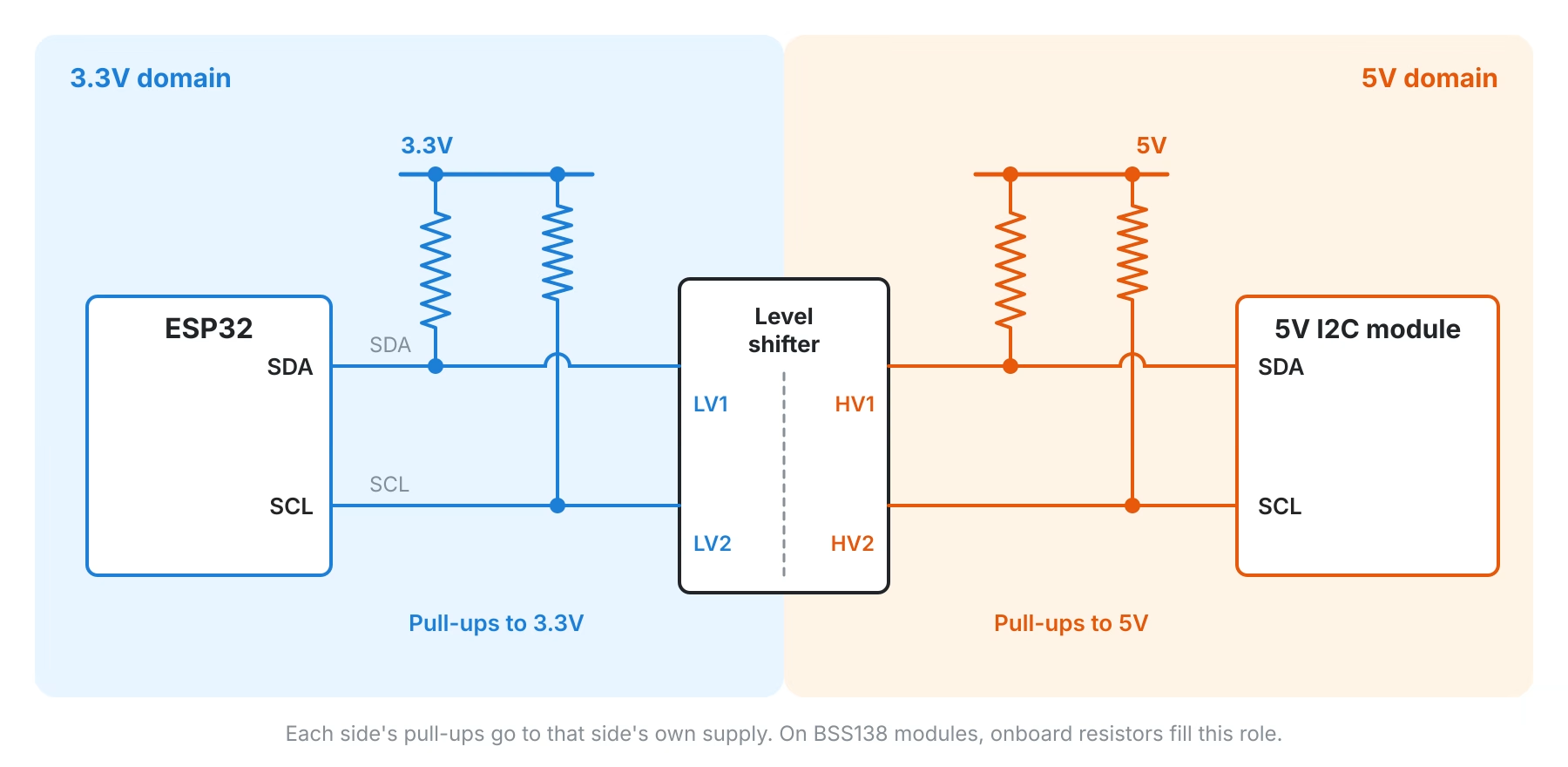
Direct 3.3V I2C is sometimes possible, provided every device's input thresholds, the pull-up voltage, and the pin ratings allow it. Check the module's actual schematic rather than relying on its advertised operating voltage.
For more on the protocol itself, see our I2C primer.
SPI: Speed and Direction Matter
SPI uses push-pull drivers for its clock and data lines and doesn't rely on pull-up resistors to create HIGH levels. That matters when choosing a level shifter. A BSS138 module might handle slow SPI signals, but its resistive rising edges distort faster ones.
Consider a 5V Arduino controlling a 3.3V SPI peripheral. SCK, MOSI, and chip select (CS) travel from the Arduino to the peripheral and need translating down. MISO travels the other way, so it needs its own path:
The SN74LVC8T245 uses a single DIR pin for all eight channels, so one chip can't carry MOSI and MISO in opposite directions. Tie its DIR pin for the outbound lines, and give MISO a separate translator, such as an SN74LVC1T45 or one channel of a 74AHCT125.
If other devices share the Arduino's MISO line, the MISO buffer must release the line when its peripheral isn't selected. With a 74AHCT125, connect the buffer's OE pin to the peripheral's active-low CS line. The buffer then drives MISO only while that peripheral is selected.
If you're new to SPI, see our SPI protocol tutorial.
Common Mistakes When Connecting 3.3V and 5V Devices
Most mixed-voltage problems trace back to a handful of recurring mistakes:
- Assuming a 5V power input means 5V-tolerant GPIO: A development board can accept 5V through a regulator while its microcontroller runs at 3.3V. Always distinguish power-input ratings from GPIO limits.
- Ignoring pull-up resistors already on sensor modules: Many I2C breakouts include onboard pull-ups tied to the module's supply voltage. Inspect the board before connecting it to a 3.3V microcontroller.
- Forgetting the common ground: Two separately powered devices need a shared ground for direct, non-isolated logic signals. Without it, the receiver may see unpredictable voltages.
- Using the same level shifter for every protocol: A BSS138 module suits I2C but not high-speed SPI. The right choice depends on signal direction, output type, speed, and capacitive loading.
- Back-powering an unpowered device: If one board is powered and the other isn't, a HIGH signal can feed current into the unpowered chip through its protection diodes. For permanent designs where this can happen, choose a translator with powered-off isolation.
- Enabling INPUT_PULLUP on the 5V side: The Uno's internal pull-ups connect to 5V. On a pin that receives an ESP32 signal, a pull-up can lift the line toward 5V whenever the ESP32's pin floats, such as during boot. Use plain INPUT mode instead.
- Wiring signals to ESP32 strapping pins: An external signal on GPIO0, GPIO2, GPIO5, GPIO12, or GPIO15 can change how the ESP32 boots. Use general-purpose pins such as GPIO18 or GPIO19 instead.
- Assuming a working circuit is electrically safe: A microcontroller might tolerate an incorrect connection for a while. That doesn't mean the voltage is within its specified limits.
How to Choose the Right Level Shifting Method
The decision comes down to three questions: Which device is transmitting? Which device is receiving? And what voltages can each pin safely produce or accept? The flow below walks through the common cases:
The table below summarizes the same choices by application:
| Application | Suggested approach |
|---|---|
| Slow 5V GPIO output to 3.3V input | Resistor divider, ideally with 1% resistors |
| Fast 5V push-pull output to 3.3V input | 5V-tolerant buffer powered at 3.3V, such as the 74LVC125A |
| 3.3V GPIO to a 5V input with a low enough VIH | Direct connection may work; check VOH against VIH |
| 3.3V output to a 5V input that needs a full 5V HIGH | 5V logic buffer, such as the 74AHCT125 |
| Mixed-voltage I2C | Bidirectional open-drain translator, such as a BSS138 module or PCA9306 |
| Low-speed 5V-to-3.3V UART | Voltage divider on the 5V TX line |
| High-speed SPI | Direction-controlled translator for SCK, MOSI, and CS, plus a separate path for MISO |
| Multiple GPIOs across voltage domains | Multi-channel translator IC |
Whichever method you choose, check both the HIGH and LOW noise margins and confirm that no pin sees more than its rated voltage.
Frequently Asked Questions
Here are answers to questions that often come up when mixing 3.3V and 5V devices.
Are ESP32 GPIO pins 5V tolerant?
No. Espressif limits the original ESP32's GPIO inputs to VDD + 0.3V, which is 3.6V on a 3.3V supply. Reduce or translate any 5V signal before it reaches an ESP32 GPIO.
Can I just use a series resistor instead of a divider?
A series resistor limits the current through the pin's protection diode, but it doesn't keep the pin within its rated voltage. Espressif doesn't specify a safe injection current for the ESP32, so a divider or buffer is the safer choice.
Does this apply to other ESP32 variants?
Generally, yes. Espressif's later chips, such as the ESP32-S2, also run 3.3V I/O and list a similar VDD + 0.3V input limit. Check the datasheet for your specific chip.
Can I connect a 3.3V sensor to an Arduino Uno?
Often, but not always. Check the sensor's output HIGH voltage against the Arduino's input thresholds. Also check whether any signal from the Arduino could expose the sensor to 5V.
Can a voltage divider convert 3.3V to 5V?
No. A resistor divider can only reduce voltage. To produce a 5V HIGH from a 3.3V signal, use a buffer or level translator.
Can I power a 3.3V sensor from an Arduino’s 3.3V pin?
Only if the pin can supply enough current. The Arduino Uno R3's 3.3V pin is rated for 50 mA. Also remember that powering a sensor at 3.3V doesn't make its signal lines safe if they have pull-ups to 5V.
Do I always need a logic level converter for I2C?
No. If every device on the bus has compatible input thresholds and the pull-up voltage stays within every device's rating, a direct connection may be fine. For mixed 3.3V and 5V buses with incompatible requirements, a dedicated I2C level translator is the safer choice.
Conclusion
Connecting 3.3V and 5V devices isn't difficult once you understand that a digital HIGH doesn't have a universal voltage.
A 5V microcontroller may recognize a 3.3V signal as HIGH, depending on its input threshold and the sender's output voltage. In the opposite direction, a 5V output can exceed the safe input voltage of a 3.3V device such as the ESP32.
A resistor divider is often an inexpensive solution for simple one-directional signals, as long as you check its worst-case output. Faster one-way signals call for a buffer powered from the right supply, which keeps edges sharp. For bidirectional buses like I2C or mixed-direction interfaces like SPI, choose a translator designed for that signal type.
Most importantly, check the datasheet before connecting two different voltage domains. With the four threshold values and a quick noise-margin check, you can mix 3.3V and 5V parts confidently in any project.
References
- Arduino Uno Rev3 documentation and specifications
- Microchip ATmega328P product page (datasheet: "DC Characteristics" table)
- Espressif ESP32 Series Datasheet ("DC Characteristics (3.3 V, 25 °C)" table)
- NXP UM10204 I2C-bus Specification and User Manual
- Texas Instruments PCA9306 I2C Level Translator
- Texas Instruments TXS0108E Voltage Translator
- Texas Instruments SN74LVC8T245 Bus Transceiver
- Texas Instruments SN74LVC1T45 Single-Bit Transceiver
- Texas Instruments SN74LVC125A Buffer
- Texas Instruments SN74AHCT125 Buffer