The ESP32-S3 is one of the most useful ESP32 boards for modern microcontroller projects. It keeps the Wi-Fi and Bluetooth features that made the original ESP32 popular, but adds better USB support, more memory options, and features aimed at AI, signal processing, and Human Interface Device applications.
If you are coming from an Arduino UNO, ESP8266, or classic ESP32 board, the ESP32-S3 can look familiar at first. It still uses GPIO pins, 3.3V logic, serial communication, PWM, I2C, SPI, and ADC inputs. But there are also important differences. Some ESP32-S3 boards have native USB. Some have PSRAM. Some have two USB ports. Some use different onboard LED pins. Some pins are connected internally to flash or PSRAM and should not be used for normal I/O.
This guide explains the ESP32-S3 in a practical and beginner-friendly manner. We will examine the ESP32-S3, its comparison to the older ESP32, how to install it in the Arduino IDE, which pins are safe to use, how USB communication works, and how to upload your first sketch.
What is the ESP32-S3?
The ESP32-S3 is a Wi-Fi and Bluetooth Low Energy microcontroller from Espressif. It is part of the ESP32 family, but it is not just a direct replacement for the original ESP32. It is a newer chip designed for connected embedded projects, USB devices, low-power IoT products, display projects, camera projects, and edge AI applications.
Common ESP32-S3 features include:
| Feature | ESP32-S3 |
|---|---|
| Wireless | 2.4 GHz Wi-Fi and Bluetooth Low Energy |
| Logic level | 3.3V |
| USB support | Native USB on supported boards |
| GPIO | Many flexible GPIO pins, depending on the module and board |
| ADC | Multiple analog-capable pins |
| PWM | Available on most usable GPIO pins |
| Common interfaces | UART, I2C, SPI, I2S, USB |
| Memory options | Varies by module; some boards include PSRAM |
| Popular use cases | IoT, displays, USB devices, keyboards, cameras, TinyML, sensor dashboards |
The exact features depend on the specific ESP32-S3 module or development board. For example, an ESP32-S3-WROOM board may expose different pins from a compact XIAO ESP32-S3 or ESP32-S3 Zero-style board. Always check the pinout of your exact board before wiring external components.
ESP32-S3 vs ESP32: What is Different?
The ESP32-S3 and the original ESP32 are both powerful Wi-Fi microcontrollers, but they are not identical.
| Feature | Original ESP32 | ESP32-S3 |
|---|---|---|
| Wi-Fi | Yes | Yes |
| Bluetooth Classic | Yes on many ESP32 chips | No, BLE only |
| Bluetooth Low Energy | Yes | Yes |
| Native USB | Usually no | Yes on supported boards |
| AI/vector instructions | No | Yes |
| GPIO behavior | Board-dependent | Board-dependent |
| Arduino IDE support | Yes | Yes |
| Best for | General IoT, Wi-Fi projects, classic ESP32 tutorials | USB projects, modern IoT, displays, cameras, BLE, TinyML |
The biggest practical difference for beginners is USB. Many classic ESP32 development boards use a USB-to-serial converter chip. On many ESP32-S3 boards, the USB port can connect directly to the microcontroller. This allows USB CDC serial, USB flashing, USB HID, USB MIDI, and other USB device projects.
However, this also creates confusion. In the Arduino IDE, you may need to enable the correct USB options before the Serial Monitor works properly.
Common ESP32-S3 Development Boards
There are many ESP32-S3 boards, and their pinouts are not always the same. Some common examples include:
| Board Type | Notes |
|---|---|
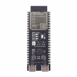
| ESP32-S3-DevKitC-1 | Official-style development board with many pins exposed |
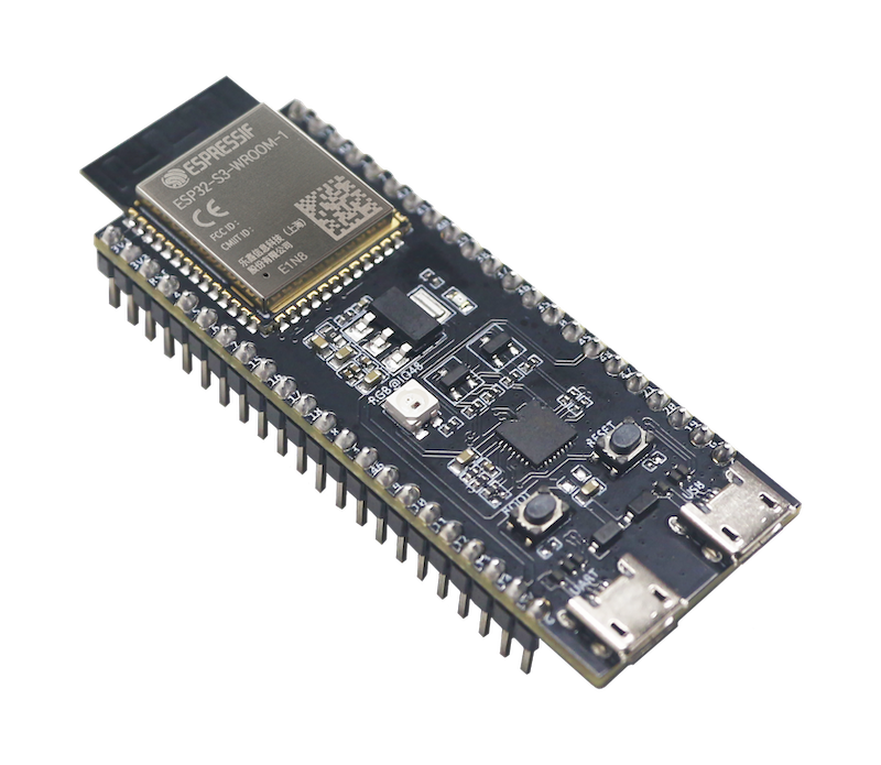
| ESP32-S3-WROOM boards | Common general-purpose ESP32-S3 modules |
| ESP32-S3 N8R8 / N16R8 boards | Usually refers to flash and PSRAM combinations |
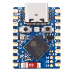
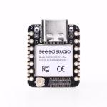
| Seeed Studio XIAO ESP32-S3 | Very small board, good for compact projects |
| XIAO ESP32-S3 Sense | Includes camera/microSD features depending on version |
| ESP32-S3 Zero-style boards | Compact boards with fewer exposed pins |
| LilyGO ESP32-S3 boards | Often includes displays, battery circuits, or special peripherals |
When following a tutorial, make sure the selected board in the Arduino IDE matches your actual hardware as closely as possible.
ESP32-S3 Board Names: What Do N8R8 and N16R8 Mean?
You may see ESP32-S3 boards labeled as N8R8, N16R8, N8, N16, or similar names. These labels usually describe the memory configuration.
For example:
| Label | Common Meaning |
|---|---|
| N8 | 8 MB flash |
| N16 | 16 MB flash |
| R8 | 8 MB PSRAM |
| N8R8 | 8 MB flash + 8 MB PSRAM |
| N16R8 | 16 MB flash + 8 MB PSRAM |
This matters because the Arduino IDE has board options for flash size, partition scheme, and PSRAM. If you select the wrong PSRAM setting, some sketches may fail or behave unpredictably, especially camera, display, or AI projects.
ESP32-S3 Pinout Basics
Click on the pins below to view information:
The ESP32-S3 has many GPIO pins, but not every pin is equally safe for beginner projects. Some pins are used for boot configuration. Some may be connected to flash or PSRAM. Some may not be exposed on your board. Some may already be used by onboard LEDs, buttons, displays, cameras, or USB circuits.
A safe beginner approach is:
- Use clearly labeled GPIO pins from your board’s pinout.
- Avoid flash/PSRAM-related pins.
- Be careful with strapping pins.
- Do not connect 5V signals directly to ESP32-S3 GPIO pins.
- Check whether your board already uses a pin for an LED, button, camera, display, or microSD card.
ESP32-S3 Pins to Be Careful With
The exact safe pins depend on your board, but these are common ESP32-S3 pin cautions:
| Pin Group | Caution |
|---|---|
| GPIO0 | Boot/strapping pin; often connected to BOOT button |
| GPIO3 | Strapping pin; use with caution |
| GPIO45 | Strapping pin; use with caution |
| GPIO46 | Strapping pin; use with caution; often input-only on some boards |
| GPIO19/GPIO20 | Often used for native USB D− and D+ |
| GPIO26–GPIO32 | Usually used for SPI flash/PSRAM on many modules |
| GPIO33–GPIO37 | May be used by Octal flash/PSRAM on some boards |
| GPIO43/GPIO44 | Often used as UART TX/RX on some ESP32-S3 boards |
| GPIO48 | Often connected to onboard RGB LED on some boards |
This is one reason ESP32-S3 tutorials can be confusing. A sketch that works on one ESP32-S3 board may not work on another if the LED pin, USB wiring, or PSRAM pins are different.
Recommended ESP32-S3 Pins for Beginner Projects
For simple digital input/output, PWM, sensors, and modules, start with pins that are exposed on your board and not reserved by onboard hardware.
Commonly usable pins on many ESP32-S3 development boards include:
| Use Case | Suggested Pins |
|---|---|
| Digital output | GPIO4, GPIO5, GPIO6, GPIO7, GPIO15, GPIO16, GPIO17, GPIO18 |
| Digital input | GPIO4, GPIO5, GPIO6, GPIO7, GPIO15, GPIO16, GPIO17, GPIO18 |
| I2C SDA/SCL | Any suitable GPIO, commonly GPIO8/GPIO9 or board-defined pins |
| SPI | Board-dependent; check the board pinout |
| PWM | Most normal output-capable GPIO pins |
| Analog input | Use ADC-capable pins shown in your board’s pinout |
| Built-in LED | Board-dependent; common examples include GPIO48, GPIO38, GPIO15, or none |
Do not assume that all ESP32-S3 boards have the same built-in LED pin. Some boards use a normal single-color LED. Some use an addressable RGB LED. Some do not have a user LED at all.
ESP32-S3 Logic Level and Power
The ESP32-S3 is a 3.3V microcontroller. This means its GPIO pins are designed for 3.3V logic, not 5V logic.
Important power rules:
| Rule | Explanation |
|---|---|
| GPIO logic level is 3.3V | Do not feed 5V directly into GPIO pins |
| 5V/VBUS pin is usually power input | It is not a 5V logic pin |
| 3V3 pin can power small external modules | Do not overload the onboard regulator |
| Use common ground | External modules must share GND with the ESP32-S3 |
| Motors and servos need separate power | Do not power motors directly from ESP32-S3 GPIO pins |
For sensors, always check whether the module supports 3.3V logic. Many I2C sensor modules work at 3.3V, but some 5V modules need level shifting.
Installing ESP32-S3 in the Arduino IDE
The easiest way to start using the ESP32-S3 is through the Arduino IDE.
Step 1: Install the Arduino IDE
Download and install the latest Arduino IDE from the official Arduino website.
Step 2: Add the ESP32 Board Package
Open Arduino IDE, then go to:
File > Preferences
In Additional Boards Manager URLs, add the ESP32 board package URL from Espressif.
Then go to:
Tools > Board > Boards Manager
Search for:
esp32
Install the package by Espressif Systems.
Step 3: Select an ESP32-S3 Board
Go to:
Tools > Board > ESP32 Arduino
Then select the board that best matches your hardware. Common options include:
ESP32S3 Dev Module
ESP32-S3-DevKitC-1
XIAO_ESP32S3
The exact board list depends on your installed ESP32 Arduino core version.
If your specific board is not listed, ESP32S3 Dev Module often works for generic ESP32-S3 boards, but you may need to manually configure flash size, PSRAM, USB mode, and upload options.
Important Arduino IDE Settings for ESP32-S3
ESP32-S3 boards have more board settings than an Arduino UNO. The most important ones are:
| Setting | What It Does |
|---|---|
| Board | Selects the target ESP32-S3 board |
| Port | Selects the USB/serial port |
| USB CDC On Boot | Enables Serial output through native USB on many boards |
| Upload Mode | Chooses how the sketch is uploaded |
| Flash Size | Must match your board’s flash |
| PSRAM | Enable only if your board has PSRAM |
| Partition Scheme | Controls app/storage memory layout |
For many ESP32-S3 boards, if your sketch uploads but the Serial Monitor shows nothing, check USB CDC On Boot. In many cases, it must be enabled for Serial.print() to appear over the native USB port.
First ESP32-S3 Blink Sketch
The Blink sketch is usually the first test for any microcontroller board. However, ESP32-S3 boards do not all use the same onboard LED pin.
Try this sketch first:
#ifndef LED_BUILTIN
#define LED_BUILTIN 48
#endif

void setup() {
  pinMode(LED_BUILTIN, OUTPUT);
}

void loop() {
  digitalWrite(LED_BUILTIN, HIGH);
  delay(500);
  digitalWrite(LED_BUILTIN, LOW);
  delay(500);
}
Upload the sketch. If the onboard LED does not blink, your board may use a different LED pin.
Try replacing the LED pin with one of these common ESP32-S3 onboard LED pins:
#define LED_BUILTIN 48
or:
#define LED_BUILTIN 38
or:
#define LED_BUILTIN 15
If your board has an addressable RGB LED, a simple digitalWrite() blink sketch may not work. Addressable LEDs usually need a library such as Adafruit NeoPixel or FastLED.
ESP32-S3 Serial Monitor Test
After Blink, test the Serial Monitor.
void setup() {
  Serial.begin(115200);
  delay(1000);

  Serial.println("ESP32-S3 Serial test");
}

void loop() {
  Serial.println("Hello from ESP32-S3!");
  delay(1000);
}
Open the Serial Monitor and set the baud rate to:
115200
If nothing appears, check these:
- Is the correct port selected?
- Is USB CDC On Boot enabled?
- Are you using the correct USB port on the board?
- Did you press reset after opening Serial Monitor?
- Is the board selected correctly?
- Are you using a charge-only USB cable?
Many ESP32-S3 upload and serial problems are caused by USB settings or USB cables.
ESP32-S3 Native USB Explained
One of the best reasons to use the ESP32-S3 is native USB support. Depending on your board and firmware, the ESP32-S3 can act as a USB device.
This opens up projects such as:
- USB keyboard
- USB mouse
- USB MIDI device
- USB serial device
- USB firmware flashing
- USB HID controller
- USB-based debugging
- USB host projects on supported boards
Some ESP32-S3 development boards have two USB ports:
| USB Port Type | Common Purpose |
|---|---|
| USB-to-serial port | Uploading and serial monitor through a converter chip |
| Native USB port | Direct USB connection to the ESP32-S3 |
On boards with two USB ports, make sure you know which port you are using. One port may be better for simple Arduino uploads, while the other may be used for native USB examples.
Reading a Button with ESP32-S3
Here is a simple button example using the internal pull-up resistor.
Connect one side of the button to the selected GPIO pin and the other side to GND.
const int buttonPin = 4;

void setup() {
  Serial.begin(115200);
  pinMode(buttonPin, INPUT_PULLUP);
}

void loop() {
  int buttonState = digitalRead(buttonPin);

  if (buttonState == LOW) {
    Serial.println("Button pressed");
  } else {
    Serial.println("Button released");
  }

  delay(200);
}
Because the internal pull-up is enabled, the pin reads HIGH when the button is not pressed and LOW when the button is pressed.
Fading an LED with PWM on ESP32-S3
The ESP32-S3 can generate PWM signals on many output-capable GPIO pins. Here is a simple LED fade example.
Connect an LED with a current-limiting resistor to a safe GPIO pin.
const int ledPin = 5;

void setup() {
  pinMode(ledPin, OUTPUT);
}

void loop() {
  for (int brightness = 0; brightness <= 255; brightness++) {
    analogWrite(ledPin, brightness);
    delay(5);
  }

  for (int brightness = 255; brightness >= 0; brightness--) {
    analogWrite(ledPin, brightness);
    delay(5);
  }
}
If your ESP32 Arduino core does not support analogWrite() for your selected board/core version, use the LEDC PWM functions instead.
Reading an Analog Sensor
The ESP32-S3 has analog input pins, but you must use pins that are ADC-capable on your specific board.
Here is a simple analog read example:
const int analogPin = 1;

void setup() {
  Serial.begin(115200);
}

void loop() {
  int value = analogRead(analogPin);

  Serial.print("ADC value: ");
  Serial.println(value);

  delay(500);
}
For a potentiometer:
- One outer pin goes to 3.3V
- The other outer pin goes to GND
- The middle pin goes to an ADC-capable GPIO
Do not connect the potentiometer to 5V if its wiper goes into an ESP32-S3 GPIO pin.
Using I2C with ESP32-S3
Unlike the Arduino UNO, the ESP32-S3 can usually assign I2C to different GPIO pins. That means SDA and SCL are often flexible.
Example I2C scanner:
#include <Wire.h>

#define SDA_PIN 8
#define SCL_PIN 9

void setup() {
  Serial.begin(115200);
  delay(1000);

  Wire.begin(SDA_PIN, SCL_PIN);

  Serial.println("ESP32-S3 I2C Scanner");
}

void loop() {
  byte error, address;
  int devices = 0;

  for (address = 1; address < 127; address++) {
    Wire.beginTransmission(address);
    error = Wire.endTransmission();

    if (error == 0) {
      Serial.print("I2C device found at 0x");
      if (address < 16) {
        Serial.print("0");
      }
      Serial.println(address, HEX);
      devices++;
    }
  }

  if (devices == 0) {
    Serial.println("No I2C devices found");
  }

  delay(5000);
}
If the scanner finds no devices, check the wiring, I2C address, power, and pull-up resistors.
Common ESP32-S3 Upload Problems
Problem: Arduino IDE Cannot Find the Board
Try these fixes:
- Use a data-capable USB cable.
- Try another USB port.
- Install the ESP32 board package.
- Hold BOOT while clicking Upload.
- Press RESET after upload starts.
- Try the other USB port if your board has two ports.
Problem: Upload Starts But Fails
Possible causes:
- Wrong board selected
- Wrong upload mode
- Bad USB cable
- BOOT button not pressed when needed
- Driver issue for USB-to-serial converter
- Wrong port selected
- External circuit pulling a boot pin to the wrong level
Disconnect external wiring while troubleshooting upload problems. A sensor or module connected to a strapping pin can prevent the ESP32-S3 from booting or entering upload mode.
Problem: Serial Monitor Shows Nothing
Try these:
- Enable USB CDC On Boot
- Select the correct port
- Set Serial Monitor to 115200 baud
- Press RESET after opening Serial Monitor
- Use the correct USB connector
- Make sure the sketch uses Serial.begin(115200);
Problem: Built-in LED Does Not Blink
Possible causes:
- Wrong LED pin
- Board uses addressable RGB LED
- Board has no onboard user LED
- LED is active-low
- Selected board definition uses a different LED_BUILTIN
Check your board’s schematic or product page.
Problem: PSRAM Sketch Fails
If your board has PSRAM, enable PSRAM in the Arduino IDE. If your board does not have PSRAM, do not enable it.
Camera, display, graphics, and AI examples often require PSRAM.
ESP32-S3 Project Ideas
Once you have the ESP32-S3 working, here are some good project ideas:
| Project | Why ESP32-S3 is a Good Fit |
|---|---|
| Wi-Fi sensor dashboard | Built-in Wi-Fi and enough processing power |
| BLE remote control | Bluetooth Low Energy support |
| USB keyboard macro pad | Native USB HID support |
| USB MIDI controller | Native USB device support |
| Web-controlled relay | Wi-Fi and GPIO control |
| Camera project | Many ESP32-S3 boards support camera modules |
| TinyML image classifier | PSRAM-equipped boards are useful for AI examples |
| Display dashboard | Good for SPI/TFT display projects |
| I2C sensor hub | Flexible I2C pins |
| Battery-powered IoT node | Suitable for low-power wireless projects with proper design |
ESP32-S3 Beginner Tips
- Do not assume all ESP32-S3 boards have the same pinout.
Always check your exact board. - Use 3.3V logic.
ESP32-S3 GPIO pins are not 5V tolerant. - Avoid flash and PSRAM pins.
Some GPIO pins are used internally and should not be used for external circuits. - Be careful with boot pins.
External pull-ups, pull-downs, LEDs, or modules can affect boot mode. - Check USB CDC settings.
Many Serial Monitor issues are caused by USB configuration. - Know your board’s memory.
Flash and PSRAM settings matter for larger projects. - Start simple.
Test Blink, Serial, button input, PWM, and I2C before building a complex project.
Frequently Asked Questions
Is ESP32-S3 better than ESP32?
For many new projects, yes. The ESP32-S3 has native USB support, modern BLE support, and features useful for AI and signal processing. However, the original ESP32 still has Bluetooth Classic support, which the ESP32-S3 does not have. If your project needs Bluetooth Classic audio or serial Bluetooth, check compatibility first.
Does ESP32-S3 support Bluetooth Classic?
No. The ESP32-S3 supports Bluetooth Low Energy, but not Bluetooth Classic. This is important if you are using old ESP32 Bluetooth Serial examples.
Can I program ESP32-S3 with Arduino IDE?
Yes. Install the ESP32 board package by Espressif in the Arduino IDE, select an ESP32-S3 board, choose the correct port, and upload your sketch.
Why is my ESP32-S3 Serial Monitor blank?
The most common causes are wrong port selection, USB CDC disabled, wrong USB connector, missing Serial.begin(), or a charge-only USB cable.
What is the ESP32-S3 built-in LED pin?
It depends on the board. Some ESP32-S3 boards use GPIO48, others use GPIO38 or GPIO15, and some use an addressable RGB LED or no user LED at all.
Can ESP32-S3 use 5V sensors?
The ESP32-S3 itself uses 3.3V logic. Some sensor modules can be powered by 5V but still output 3.3V signals, while others output 5V signals. Do not connect a 5V signal directly to an ESP32-S3 GPIO pin.
Which ESP32-S3 board should beginners buy?
A general ESP32-S3 DevKit-style board is a good starting point because it exposes many pins and is easier to use on a breadboard. If you want camera or TinyML projects, choose a board with PSRAM and camera support.
Conclusion
The ESP32-S3 is a powerful upgrade for many ESP32 projects, especially if you want native USB, BLE, more memory options, camera support, display projects, or TinyML experiments. It is still beginner-friendly, but it has more board-specific details than an Arduino UNO or even a classic ESP32.
The most important things to remember are:
- Select the correct ESP32-S3 board in the Arduino IDE.
- Use the correct USB CDC and upload settings.
- Check the actual pinout of your board.
- Avoid pins used by flash, PSRAM, USB, or boot configuration.
- Use 3.3V logic only.
- Do not assume the onboard LED pin is the same on every ESP32-S3 board.
Once you understand these details, the ESP32-S3 becomes one of the most flexible microcontroller boards for Wi-Fi, BLE, USB, sensor, display, and embedded AI projects.


 Board for the First Time")