
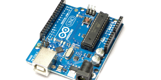
The Arduino UNO is arguably the most popular Arduino board currently available. This Arduino UNO Pinout diagram reference will hopefully help you get the most out of this board:

Arduino UNO Pinout Description
The Arduino UNO board is divided into digital, analog, and power pins. There are pins with secondary functions as listed below. Secondary pins are mostly communications pins such as I2C and SPI.
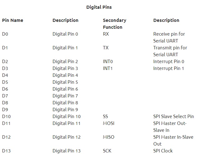
Digital Pins
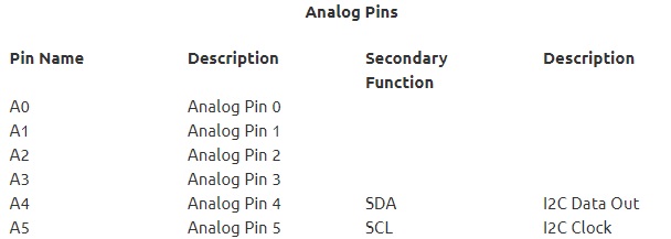
Analog Pins
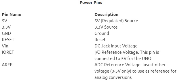
Power Pins
Also, notice that the ATMega pins for each Arduino pin are also provided in the diagram above. For details on how to use these pins, see Arduino Port Manipulation.
Arduino UNO Rev3 Schematic Diagram
For those who want to dig deeper into understanding the Arduino UNO board, I suggest you look into its schematic diagram:
(Click to view larger image)
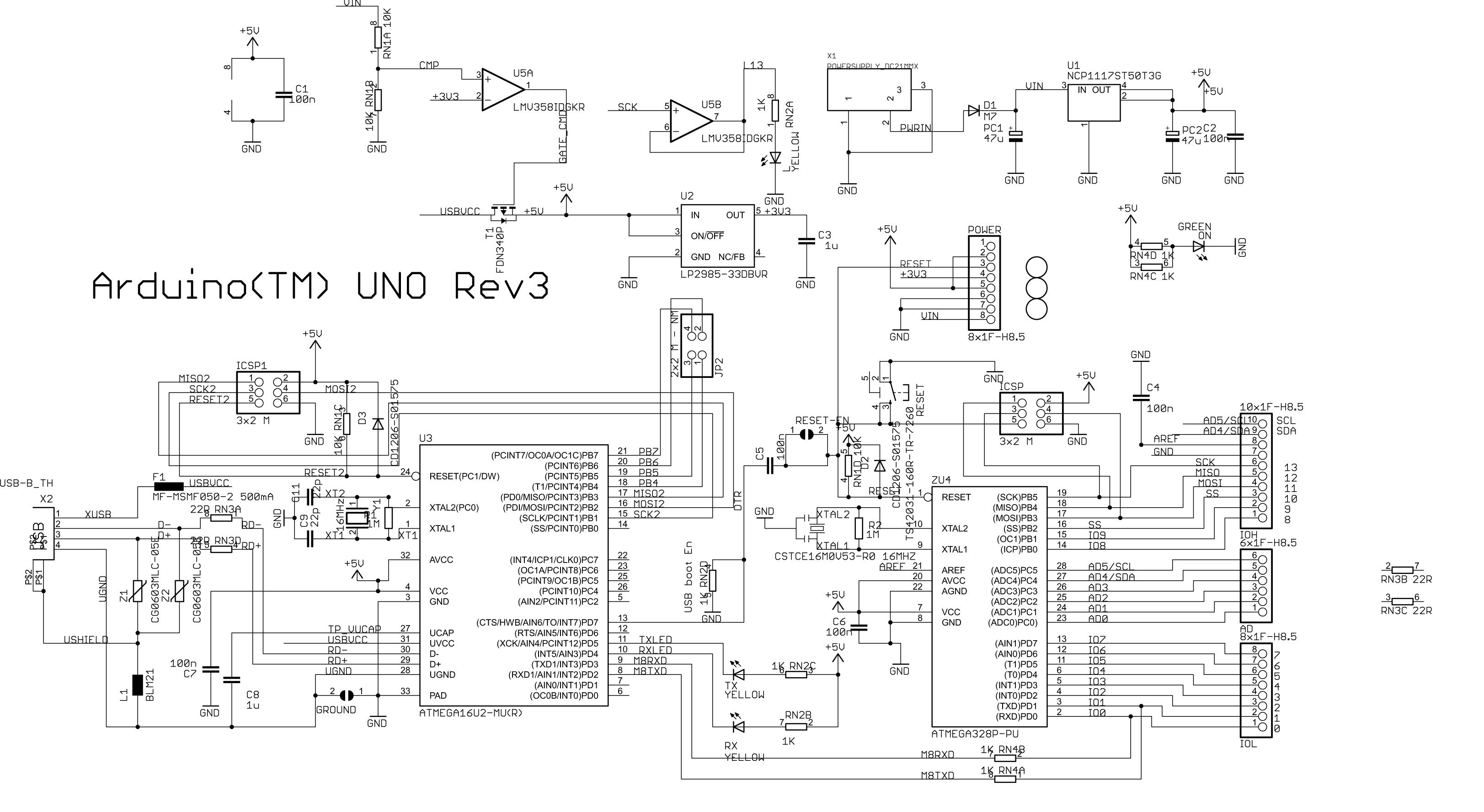
The schematic diagram above is also helpful when you want to build your own Arduino.


I'd like to find out more? I'd want to find out more details.