
The HC-05 is a common Bluetooth module used in many microcontroller projects. Here's a compilation of all HC-05 Bluetooth AT Commands. For beginners, see Arduino Bluetooth.
Setting HC-05 to AT Command Mode
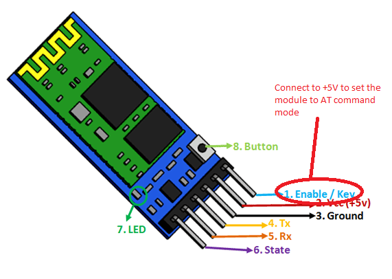
By default, the HC-05 is configured in data mode. In this mode, the module acts like a serial bridge. To put into AT command mode the KEY pin must be set (high).
However, there are modules where the KEY pin is missing or is not wired to the actual KEY pin of the IC. To solve this, wire pin 34 of the IC to 3.3 V:
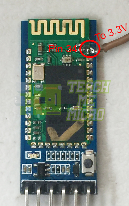
The HC-05 is now in command mode if the red LED flashes once every two seconds.
The following commands require that the HC-05 is connected to the Arduino as a serial device. Below is an example wiring diagram and sketch/code:

#include <SoftwareSerial.h>

SoftwareSerial Bluetooth(7,8);

void setup() {
  Serial.begin(9600);
  Bluetooth.begin(9600);
}

void loop() {
  while (Serial.available()) {
      delay(1);
      Bluetooth.write(Serial.read());
  }
  while (Bluetooth.available()) {
       Serial.write(Bluetooth.read());
  }
}
Test command
| Command | Response | Parameter |
|---|---|---|
| AT | OK | - |
Reset
| Command | Response | Parameter |
|---|---|---|
| AT+RESET | OK | - |
Get firmware version
| Command | Response | Parameter |
|---|---|---|
| AT+VERSION? | +VERSION:<Param>
OK |
Param : firmware version |
Example:
AT+VERSION?
+VERSION:2.0-20100601
OK
Restore default
| Command | Response | Parameter |
|---|---|---|
| AT+ORGL | OK | - |
Default state:
Slave mode, pin code :1234, device name: H-C-2010-06-01 ,Baud 38400bits/s.
Get module address
| Command | Response | Parameter |
|---|---|---|
| AT+ADDR? | +ADDR:<Param> OK | Param: address of Bluetooth module |
Bluetooth address: NAP: UAP : LAP
Example:
AT+ADDR?
+ADDR:1234:56:abcdef
OK
Set/Check module name:
| Command | Response | Parameter |
|---|---|---|
| AT+NAME=<Param> | OK | Param: Bluetooth module name (Default :HC-05) |
| AT+NAME? | +NAME:<Param>
OK or FAIL |
Example:
AT+NAME=HC-05      ;set the module name to “HC-05”
OK
AT+NAME?
+NAME: HC-05
OK
Get the Bluetooth device name:
| Command | Response | Parameter |
|---|---|---|
| AT+RNAME?<Param1> | +NAME:<Param2>
OK or FAIL |
Param1,Param 2 : the address of Bluetooth device |
Example: (Device address 00:02:72:od:22:24,name:HC-05)
AT+RNAME? 0002,72,od2224
+RNAME:HC-05
OK
Set/Check module mode:
| Command | Response | Parameter |
|---|---|---|
| AT+ROLE=<Param> | OK | 0 - Slave
1 - Master 2 - Slave-Loop |
| AT+ ROLE? | +ROLE:<Param>
OK |
Set/Check device class
| Command | Response | Parameter |
|---|---|---|
| AT+CLASS=<Param> | OK | Param: Device Class |
| AT+CLASS? | +CLASS:<Param>
OK or FAIL |
Set/Check GIAC (General Inquire Access Code)
| Command | Response | Parameter |
|---|---|---|
| AT+IAC=<Param> | OK
or FAIL |
Param: GIAC (Default : 9e8b33) |
| AT+IAC | +IAC:<Param>
OK |
Example:
AT+IAC=9e8b3f
OK
AT+IAC?
+IAC: 9e8b3f
OK
Set/Check -- Query access patterns
| Command | Response | Parameter |
|---|---|---|
| AT+INQM=<Param>,<Param2>,
<Param3> |
OK
or FAIL |
Param:
0 -- inquiry_mode_standard 1 -- inquiry_mode_rssi Param2: Maximum number of Bluetooth devices to respond to Param3: Timeout (1-48 : 1.28s to 61.44s) |
| AT+ INQM? | +INQM :<Param>,<Param2>,
<Param3> OK |
Example:
AT+INQM=1,9,48
OK
AT+INQM
+INQM:1, 9, 48
OK
Set/Check PIN code:
| Command | Response | Parameter |
|---|---|---|
| AT+PSWD=<Param> | OK | Param: PIN code
(Default 1234) |
| AT+PSWD? | + PSWD : <Param>
OK |
Set/Check serial parameter:
| Command | Response | Parameter |
|---|---|---|
| AT+UART=<Param>,<Param2>,< Param3> | OK | Param1: Baud
Param2: Stop bit Param3: Parity |
| +UART=<Param>,<Param2>,
<Param3> OK |
Example:
AT+UART=115200,1,2,
OK
AT+UART?
+UART:115200,1,2
OK
Set/Check connect mode:
| Command | Response | Parameter |
|---|---|---|
| AT+CMODE=<Param> | OK | Param:
0 - connect fixed address 1 - connect any address 2 - slave-Loop |
| + CMODE:<Param>
OK |
Set/Check fixed address:
| Command | Response | Parameter |
|---|---|---|
| AT+BIND=<Param> | OK | Param: Fixed address
(Default 00:00:00:00:00:00) |
| AT+BIND? | + BIND:<Param>
OK |
|
Example:
AT+BIND=1234,56,abcdef
OK
AT+BIND?
+BIND:1234:56:abcdef
OK
Set/Check LED I/O
| Command | Response | Parameter |
|---|---|---|
| AT+POLAR=<Param1,<Param2> | OK | Param1:
0- PIO8 low drive LED 1- PIO8 high drive LED Param2: 0- PIO9 low drive LED 1- PIO9 high drive LED |
| + POLAR=<Param1>,<Param2>
OK |
Set PIO output
| Command | Response | Parameter |
|---|---|---|
| AT+PIO=<Param1>,<Param2> | OK | Param1: PIO number
Param2: PIO level 0- low 1- high |
Example:
;PIO10 output high level
AT+PI0=10,1
OK
Set/Check – scan parameter
| Command | Response | Parameter |
|---|---|---|
| AT+IPSCAN=<Param1>,<Param2
>,<Param3>,<Param4> |
OK | Param1: Query time interval
Param2: Query duration Param3: Paging interval Param4: Call duration |
| AT+IPSCAN? | +IPSCAN:<Param1>,<Param2>,<Param3>,<Param4> OK |
Example:
AT+IPSCAN =1234,500,1200,250
OK
AT+IPSCAN?
+IPSCAN:1234,500,1200,250
Set/Check – SNIFF parameter
| Command | Response | Parameter |
|---|---|---|
| AT+SNIFF=<Param1>,<Param2>,
<Param3>,<Param4> |
OK | Param1: Max time
Param2: Min time Param3: Retry time Param4: Time out |
| AT+SNIFF? | +SNIFF:<Param1>,<Param2>,<Param3>,<Param4>
OK |
Set/Check security mode
| Command | Response | Parameter |
|---|---|---|
| AT+SENM=<Param1>,<Param2> | OK
or FAIL |
Param1:
0 --sec_mode0+off AT+ SENM? + SENM:<Param1>,<Param2> 1——sec_mode1+non_secure 2 -- sec_mode2_service 3 -- sec_mode3_link 4 -- sec_mode_unknown Param2: 0 -- hci_enc_mode_off 1 -- hci_enc_mode_pt_to_pt 2 -- hci_enc_mode_pt_to_pt_and_bcast |
Delete Authenticated Device
| Command | Response | Parameter |
|---|---|---|
| AT+PMSAD=<Param> | OK | Param:
Authenticated Device Address |
Example:
AT+PMSAD =1234,56,abcdef
OK
Delete All Authenticated Device
| Command | Response | Parameter |
|---|---|---|
| AT+ RMAAD | OK |
Search Authenticated Device
| Command | Response | Parameter |
|---|---|---|
| AT+FSAD=<Param> | OK
or FAIL |
Param: Device address |
Get Authenticated Device Count
| Command | Response | Parameter |
|---|---|---|
| AT+ADCN? | +ADCN:<Param>
OK |
Param: Device Count |
Most Recently Used Authenticated Device
| Command | Respond | Parameter |
|---|---|---|
| AT+MRAD? | + MRAD:<Param>
OK |
Param: Recently Authenticated Device Address |
Get the module working state
| Command | Response | Parameter |
|---|---|---|
| AT+ STATE? | + STATE:<Param>
OK |
Param:
“INITIALIZED” “READY” “PAIRABLE” “PAIRED” “INQUIRING” “CONNECTING” “CONNECTED” “DISCONNECTED” “NUKNOW” |
Initialize the SPP profile lib
| Command | Response | Parameter |
|---|---|---|
| AT+INIT | OK
or FAIL |
- |
Inquiry Bluetooth Device
| Command | Response | Parameter |
|---|---|---|
| AT+INQ | +INQ: <Param1>, <Param2>, <Param3>
…. OK |
Param1:Address
Param2:Device Class Param3:RSSI Signal strength |
Example:
AT+INIT
OK
AT+IAC=9e8b33
OK
AT+CLASS=0
AT+INQM=1,9,48
AT+INQ
+INQ:2:72:D2224,3E0104,FFBC
+INQ:1234:56:0,1F1F,FFC1
+INQ:1234:56:0,1F1F,FFC0
+INQ:1234:56:0,1F1F,FFC1
+INQ:2:72:D2224,3F0104,FFAD
+INQ:1234:56:0,1F1F,FFBE
+INQ:1234:56:0,1F1F,FFC2
+INQ:1234:56:0,1F1F,FFBE
+INQ:2:72:D2224,3F0104,FFBC OK
Cancel Inquiring Bluetooth Device
| Command | Response | Parameter |
|---|---|---|
| AT+ INQC | OK | - |
Equipment Matching
| Command | Response | Parameter |
|---|---|---|
| AT+PAIR=<Param1>,<Param2> | OK
or FAIL |
Param1:Device Address
Param2:Time out |
Connect Device
| Command | Response | Parameter |
|---|---|---|
| AT+LINK=<Param> | OK
or FAIL |
Param:Device Address |
Example:
AT+FSAD=1234,56,abcdef
OK
AT+LINK=1234,56,abcdef
OK
Disconnect
| Command | Response | Parameter |
|---|---|---|
| AT+DISC | +DISC:SUCCESS
OK or +DISC:LINK_LOSS OK or +DISC:NO_SLC OK or +DISC:TIMEOUT OK or +DISC:ERROR OK |
Param:Device Address |
Energy-saving mode
| Command | Response | Parameter |
|---|---|---|
| AT+ENSNIFF=<Param> | OK | Param:Device Address |
Exerts Energy-saving mode
| Command | Response | Parameter |
|---|---|---|
| AT+ EXSNIFF =<Param> | OK | Param:Device Address |
Pairing Two HC-05 Modules
Use an FTDI USB to Serial converter to configure the bluetooth module once it’s in command mode (how to set in command mode). Then use Arduino’s serial monitor to send out commands. The default baud rate for command mode is 38400. One module is the master device while the other is the slave device. Pairing configuration is done through the master device.
Step 1: Check if the HC-05 master is in command mode:
AT
> OK
Step 2: Reset the configurations to their default values:
AT+ORGL
> OK
Step 3: Set the module to master:
AT+ROLE=1
> OK
Step 4: Reset the module:
AT+RESET
> OK
Step 5: Wait, then initialize:
AT+INIT
> OK
Step 6: Forget all the previous connections:
AT+RMAAD
> OK
Step 7: Determine MAC address of slave device. Set slave device to command mode and issue command:
AT+INQ
> +INQ:98D3:31:FC20A9,1F00,7FFF
Here, it shows that the slave device has a MAC address of 98D3:31:FC20A9. The 1F00 is the device class while the 7FFF is the received signal strength indicator (RSSI).
Step 8: Back to master module; pair with the slave device:
AT+PAIR=98D3,31,FC20A9,20
> OK
After pairing, the LED on the master module will start flashing with about two seconds of pause.
Step 9: Bind the master and slave devices:
AT+BIND=98D3,31,FC20A9
> OK
Step 10: Link the two devices:
AT+LINK=98D3,31,FC20A9
> OK
If successful, both the master and slave device's LED will now blink twice followed by about two seconds of pause.


Hello, I'm working on a projet:
i have an arduino uno and 2 BT modules (HC-05 & HM-10)
I should be able via (arduino+ Bluetooth module) to discover all nearby smartphones (android & ios) then to notify them (send message or picture) but without installing any app or doing any config on those smartphones (only bluetooth should be activated on them).
The HC-05 doesn't support the AT+DISC command and the BLE HM-10 discover only BLE devices (no smartphone discovered)
Is there any way to do this using this hardware?
Should i get a specific Bluetooth module ? if yes which model?
Hi,
You should post relevant code to use with this.
Jack
Thank you fpr your good tutorial.
Howevere, there is a small bug in it...
void setup() {
Serial.begin(9600);
Bluetooth.begin(38400); // only works with 38400!
}
Matthias