The ESP32-S3 is commonly powered through its USB port while programming and testing. However, USB power is not always practical for projects installed outdoors, mounted on walls, or placed far from an electrical outlet.
In this tutorial, we will build an ESP32-S3 AA battery power supply using two AA cells and an MT3608 boost converter. We will also add an optional battery-voltage monitor and use deep sleep to make the batteries last longer.
The short answer is that an ESP32-S3 can run from AA batteries, but the batteries should not normally be connected directly to the development board. The voltage must remain stable, and the power circuit must handle the short current bursts produced when the ESP32-S3 uses Wi-Fi or Bluetooth.
This tutorial assumes an ESP32-S3 development board similar to the Espressif ESP32-S3-DevKitC-1. Other ESP32-S3 boards may have different regulators, power LEDs, USB circuits, pin labels, and power-input arrangements. Check your board’s schematic before applying power through its 3V3 pin.
Can an ESP32-S3 Run on AA Batteries?
Yes. Two AA batteries can power an ESP32-S3 when used with a suitable voltage converter. The ESP32-S3 chip normally operates from a 3.3 V supply. Its acceptable supply range is approximately 3.0 V to 3.6 V. The power source must also handle the ESP32-S3’s brief current peaks when its radio begins transmitting.
A pair of alkaline AA batteries has a nominal voltage of:

At first glance, 3.0 V may appear close enough to the ESP32-S3’s operating voltage. The problem is that battery voltage does not remain fixed. A fresh alkaline cell may measure above 1.5 V without a load. Its voltage then gradually falls as the battery discharges. The terminal voltage can also drop suddenly when the ESP32-S3 draws a high-current pulse. Directly connecting two AA cells to the 3V3 pin may therefore work initially but become unreliable as the batteries discharge. The ESP32-S3 may reset when Wi-Fi starts, fail to boot, or stop operating long before the batteries are completely empty.
To avoid this problem, we will use an MT3608 boost converter adjusted to provide a regulated 3.3 V output.
What Is the MT3608?
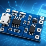
The MT3608 is a small step-up or boost converter. A boost converter takes a lower DC voltage and raises it to a higher regulated voltage.
Common MT3608 breakout modules include:
- An MT3608 switching-regulator IC
- An inductor
- A Schottky diode
- Input and output capacitors
- A multi-turn adjustment potentiometer
- IN+, IN−, OUT+, and OUT− connection pads
The MT3608 IC has an input-voltage range of approximately 2 V to 24 V and an adjustable output. Its switching frequency is 1.2 MHz. For this project, the module raises the changing voltage from two AA cells to a regulated 3.3 V:

The MT3608 is inexpensive and widely available, which makes it practical for a prototype or hobby project.
The MT3608 Is Boost-Only
An important limitation is that the MT3608 can only raise voltage. It cannot reduce a voltage that is higher than the desired output. For example, an MT3608 should not be used to convert a three-cell alkaline battery pack from approximately 4.5 V down to 3.3 V. That would require a buck converter or buck-boost converter instead. Two alkaline or two NiMH AA cells remain below the desired 3.3 V output during normal use, so they are suitable for this circuit.
MT3608 Current Ratings
Many online listings describe an MT3608 module as a “2 A boost converter.” This does not necessarily mean that the module can continuously supply 2 A at its output under all conditions.
The available output current depends on:
- Input voltage
- Output voltage
- Converter efficiency
- Inductor rating
- Diode rating
- PCB layout
- Cooling
- Battery condition and internal resistance
At a low battery voltage, the converter must draw more current from the batteries than it delivers at its output.
Ignoring converter losses for a moment:

After including converter efficiency:

For example, supplying 500 mA at 3.3 V from a 2.0 V battery pack at 85% efficiency would require approximately:


The ESP32-S3 will not continuously draw 500 mA in a typical sensor project, but the batteries and converter must tolerate its short radio-current peaks.
AA Battery Configurations for the MT3608
Here is what happens with common AA battery arrangements:
| Battery configuration | Approximate nominal voltage | Suitable with MT3608? |
|---|---|---|
| One alkaline AA | 1.5 V | No; below the MT3608’s specified input range |
| Two alkaline AAs | 3.0 V | Yes; boost to 3.3 V |
| Three alkaline AAs | 4.5 V | No; the MT3608 cannot step down to 3.3 V |
| Four alkaline AAs | 6.0 V | No; use a step-down converter |
| Two NiMH AAs | 2.4 V | Yes; boost to 3.3 V |
| Three NiMH AAs | 3.6 V | No; the pack may be above the required output |
Two AA cells are therefore the most convenient arrangement for this MT3608 circuit.
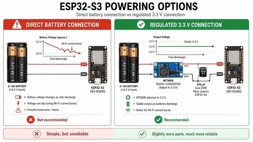
Because the MT3608 requires approximately 2 V at its input, the converter will eventually stop operating when a two-cell pack falls to about 1 V per cell.
Required Components
For the basic ESP32-S3 AA battery circuit, you will need:
- ESP32-S3 development board
- MT3608 adjustable boost-converter module
- Two-cell AA battery holder
- Two matching AA batteries
- On/off switch
- 470 µF electrolytic capacitor rated for at least 6.3 V
- 0.1 µF ceramic capacitor
- Multimeter
- Jumper wires or soldered connections
For battery-voltage measurement, you will also need:
- Two 100 kΩ resistors
- One optional 0.1 µF capacitor
Use batteries of the same type, brand, capacity, and approximate age. Do not mix alkaline batteries with rechargeable batteries in the same holder.
Adjusting the MT3608 to 3.3 V
The MT3608 is an adjustable converter. It must be configured before it is connected to the ESP32-S3.
Do not connect the MT3608 output to the ESP32-S3 until you have measured and adjusted its output voltage. An incorrectly adjusted module can output a voltage high enough to damage the board.
Follow these steps:
- Insert the two AA batteries into the holder.
- Connect the battery holder’s positive wire to MT3608 IN+.
- Connect the battery holder’s negative wire to MT3608 IN−.
- Set your multimeter to DC voltage.
- Measure between MT3608 OUT+ and OUT−.
- Turn the adjustment potentiometer slowly while watching the multimeter.
- Stop when the output reads approximately 3.30 V.
- Disconnect the batteries before wiring the ESP32-S3.
The potentiometer on many MT3608 modules is multi-turn. It may require several rotations before the output voltage visibly changes. Do not assume that every module adjusts in the same direction. Watch the multimeter while turning the potentiometer.
ESP32-S3 AA Battery Wiring Diagram
After adjusting the MT3608 to 3.3 V, connect the complete circuit as follows:
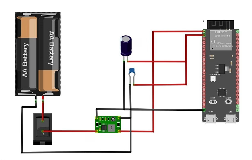
Observe the polarity of the electrolytic capacitor:
- Capacitor positive lead to MT3608 OUT+
- Capacitor negative lead to ground
The 470 µF capacitor helps supply short bursts of current when the ESP32-S3 radio begins transmitting. The 0.1 µF ceramic capacitor helps suppress higher-frequency noise. Install the capacitors close to the ESP32-S3 power pins rather than close to the battery holder. Long wires add resistance and inductance, reducing the capacitors’ ability to support fast current pulses.
Why We Connect the MT3608 to the 3V3 Pin
Most ESP32-S3 development boards include an onboard regulator that converts USB or 5 V input to 3.3 V.
One option would be to adjust the MT3608 to 5 V and connect it to the board’s 5V input. However, the power would pass through two conversion stages:

Each conversion stage wastes some energy.
By adjusting the MT3608 to 3.3 V and connecting it directly to the 3V3 pin, we bypass the development board’s onboard regulator:

The disadvantage is that the board no longer has another regulator between the MT3608 and the ESP32-S3. The MT3608 output must therefore be adjusted accurately and checked before every major wiring change.
Important USB Power Warning
Disconnect the AA battery supply before connecting the ESP32-S3 to USB unless the board or external circuit includes proper power-source isolation.
Connecting USB power and an external 3.3 V supply at the same time may cause current to flow backward into one of the power sources.
A simple approach during development is:
- Switch off or disconnect the AA battery holder.
- Connect USB and upload the sketch.
- Disconnect USB.
- Reconnect or switch on the battery supply.
A more advanced design can use:
- Schottky-diode isolation
- An ideal-diode controller
- A load switch
- A power multiplexer
- A jumper that selects USB or battery power
Adding an ESP32-S3 Battery Voltage Monitor
The ESP32-S3 can measure the battery voltage using one of its ADC pins. The measurement must be taken from the battery side of the MT3608. Measuring the converter output would normally show approximately 3.3 V even as the batteries discharge.
For a two-cell AA pack, use the following voltage divider:
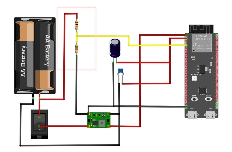
GPIO4 is an ADC-capable pin on the ESP32-S3 and corresponds to ADC1 channel 3.
The two equal resistors divide the battery voltage by two:

Therefore:

A fresh two-cell alkaline pack measuring 3.2 V produces approximately:

An optional 0.1 µF capacitor from GPIO4 to ground can reduce noise and help stabilize the ADC reading. This is especially useful because the two 100 kΩ resistors create a relatively high-impedance source for the ADC.
The resistor divider continuously draws a small current:


This is small compared with the consumption of a normal ESP32-S3 development board. However, it can become significant in a highly optimized low-power design. On a custom PCB, the voltage divider can be enabled only when a measurement is required by using a MOSFET or analog switch.
ESP32-S3 AA Battery and Deep-Sleep Code
The following Arduino sketch reads the AA battery-pack voltage and then places the ESP32-S3 into deep sleep for ten minutes.
#include <Arduino.h>

#define BATTERY_ADC_PIN       4
#define SLEEP_TIME_SECONDS    600

const float R1 = 100000.0;
const float R2 = 100000.0;

float readBatteryVoltage()
{
  const int numberOfSamples = 32;
  uint32_t totalMillivolts = 0;

  for (int i = 0; i < numberOfSamples; i++)
  {
    totalMillivolts += analogReadMilliVolts(BATTERY_ADC_PIN);
    delay(5);
  }

  float adcMillivolts =
      totalMillivolts / (float)numberOfSamples;

  float adcVoltage = adcMillivolts / 1000.0;

  // Reconstruct the original battery voltage.
  float batteryVoltage =
      adcVoltage * ((R1 + R2) / R2);

  return batteryVoltage;
}

void setup()
{
  Serial.begin(115200);
  delay(1000);

  analogReadResolution(12);
  analogSetPinAttenuation(BATTERY_ADC_PIN, ADC_11db);

  float batteryVoltage = readBatteryVoltage();

  Serial.print("AA battery pack voltage: ");
  Serial.print(batteryVoltage, 2);
  Serial.println(" V");

  /*
   * Read sensors or transmit data here.
   *
   * Keep this section as short as possible.
   * Wi-Fi, Bluetooth and sensors consume much
   * more current than deep sleep.
   */

  Serial.println("Entering deep sleep...");
  Serial.flush();

  esp_sleep_enable_timer_wakeup(
      (uint64_t)SLEEP_TIME_SECONDS * 1000000ULL
  );

  esp_deep_sleep_start();
}

void loop()
{
  // The ESP32-S3 restarts setup() after waking
  // from deep sleep.
}
The Arduino-ESP32 API provides analogReadMilliVolts(), which returns a calibrated voltage value rather than a raw ADC count.
The 11 dB attenuation setting increases the input range available to the ADC. The divided battery voltage should remain well below the ESP32-S3 ADC pin’s maximum level.
How the Deep-Sleep Code Works
The ESP32-S3 executes setup() after power-up and after every deep-sleep wake-up.
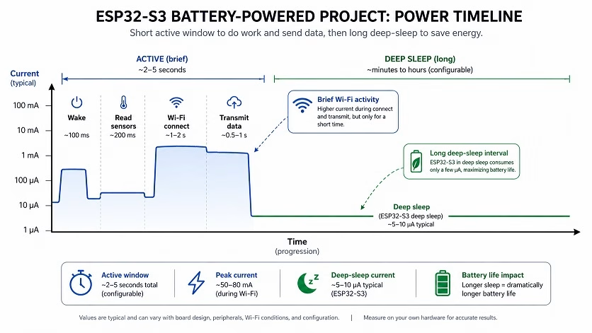
The program performs the following sequence:
- Configures the ADC.
- Reads the AA battery-pack voltage.
- Performs the required sensor or communication task.
- Configures a ten-minute wake-up timer.
- Enters deep sleep.
- Restarts when the timer expires.
The sleep duration is configured here:
#define SLEEP_TIME_SECONDS 600For a five-minute interval, change it to:
#define SLEEP_TIME_SECONDS 300For a one-hour interval:
#define SLEEP_TIME_SECONDS 3600Deep sleep powers down the ESP32-S3 CPUs and most digital peripherals while retaining selected RTC circuitry. The ESP32-S3 chip itself can reach a deep-sleep current of only a few microamps under datasheet conditions. A complete development board will normally consume more because it may also contain:
- A voltage regulator
- USB-to-UART circuitry
- USB interface circuitry
- A power indicator LED
- An addressable RGB LED
- Flash memory
- PSRAM
- Pull-up resistors
- Other support components
The MT3608 module also consumes current while operating, even when the ESP32-S3 is asleep.
Is the MT3608 Good for Deep-Sleep Projects?
The MT3608 is suitable for learning, prototyping, and inexpensive battery-powered projects. However, it is not necessarily the best converter for an ultra-low-power sensor node.
The total sleep current includes:
- ESP32-S3 development-board sleep current
- MT3608 operating current
- Any indicator LED on the MT3608 module
- Battery-monitor divider current
- Sensor standby current
- Leakage through connected peripherals
Some generic MT3608 modules include an indicator LED that remains on continuously. Even a small LED current can become significant when the ESP32-S3 spends most of its time sleeping. For a project intended to run for many months or years, consider a boost converter designed specifically for low-quiescent-current operation.
The MT3608 remains useful for this tutorial because it is:
- Inexpensive
- Widely available
- Easy to adjust
- Easy to mount on a breadboard or prototype board
- Capable of supplying an ESP32-S3 when properly selected and tested
Estimating ESP32-S3 AA Battery Runtime
Battery runtime depends more on average current than on the highest current peak.
A basic runtime estimate is:

Suppose the ESP32-S3:
- Draws 120 mA while awake
- Remains awake for five seconds
- Wakes every ten minutes
- Draws 0.3 mA from the 3.3 V rail while sleeping
Its average current on the regulated 3.3 V rail is approximately:


Assuming an average battery voltage of 2.4 V and an MT3608 efficiency of 85%:


Using a conservative usable battery capacity of 2000 mAh:


This is approximately 40 days.
However, this simplified calculation does not include the MT3608 module’s own operating current. Suppose the converter module and its indicator LED draw an additional 1 mA from the battery pack:


The estimated runtime would then become:


This is approximately 27 days.
This example shows why converter idle current matters in a deep-sleep project.
Actual runtime may be lower because of:
- MT3608 quiescent and indicator-LED current
- Battery internal resistance
- Low-temperature operation
- Wi-Fi connection time
- Sensor consumption
- Development-board LEDs
- Battery age
- Reduced alkaline capacity at higher discharge currents
- The MT3608’s approximately 2 V minimum input
- Conversion losses that change with load and battery voltage
The best approach is to measure the current of the complete circuit using the actual batteries, converter module, sensors, development board, and firmware.
Alkaline or Rechargeable AA Batteries?
Both alkaline and NiMH AA batteries can be used with the MT3608.
Alkaline AA Batteries
Alkaline batteries have a nominal voltage of 1.5 V per cell. Two cells produce a nominal 3.0 V, which the MT3608 can raise to 3.3 V. Alkaline cells are widely available and have a relatively low self-discharge rate. However, their voltage continuously falls during use, and their effective capacity decreases under heavier loads. The high current pulses produced by Wi-Fi may cause a larger temporary voltage drop when alkaline batteries are old, cold, or partially discharged.
NiMH Rechargeable AA Batteries
NiMH batteries typically have a nominal voltage of 1.2 V per cell. Two cells therefore provide approximately:

The MT3608 raises this to 3.3 V. NiMH batteries generally handle repeated high-current pulses better than ordinary alkaline batteries and can be recharged many times. For a frequently used wireless sensor, NiMH cells may be more economical. Low-self-discharge NiMH batteries are especially useful when the device spends long periods asleep.
Improving ESP32-S3 AA Battery Life
Use Deep Sleep
Do not leave the ESP32-S3 running continuously if it only needs to take a measurement every few minutes. Deep sleep normally provides a much larger improvement than simply reducing the CPU frequency while the chip remains awake.
Keep Wi-Fi Sessions Short
Connecting to Wi-Fi and transmitting data consume considerably more current than sleeping.
A battery-powered application should normally:
- Wake up.
- Read its sensors.
- Connect to the network.
- Transmit its data.
- Disconnect or shut down the radio.
- Return to deep sleep.
Remove or Disable Power LEDs
A power LED drawing even 1 mA becomes significant when the ESP32-S3 spends most of its time in deep sleep. Inspect both the ESP32-S3 board and the MT3608 module for always-on LEDs. Some boards allow the LED resistor to be removed. Others require cutting a trace. Only modify a board after inspecting its schematic and PCB connections.
Turn Sensors Off While Sleeping
Some sensors continue drawing current even while the ESP32-S3 is asleep. A load switch, P-channel MOSFET, or regulator-enable pin can disconnect sensor power before deep sleep.
Keep the Wires Short
Long, thin wires add resistance. A high current pulse can produce a temporary voltage drop across them:

Keep the battery, MT3608, capacitor, and ESP32-S3 power connections short and secure.
Use a Low-Power Converter for Long Deployments
The MT3608 is useful for prototyping, but a low-quiescent-current fixed-output converter is a better choice when maximizing runtime is more important than minimizing component cost.
Move to a Custom PCB
Development boards are excellent for prototyping, but their USB interface, LEDs, regulator, and support circuitry are not always optimized for battery operation. A custom PCB using an ESP32-S3 module and a low-power converter can achieve much lower sleep current.
Troubleshooting the ESP32-S3 MT3608 Circuit
The ESP32-S3 Resets When Wi-Fi Starts
This is usually caused by the 3.3 V rail dropping during a radio-current burst.
Check the following:
- MT3608 output voltage under load
- Battery condition
- Battery-holder contacts
- Wire length and thickness
- Output-capacitor value and placement
- Solder joints
- MT3608 module quality
Place the 470 µF capacitor close to the ESP32-S3. Measure the 3.3 V rail while the ESP32-S3 starts Wi-Fi rather than measuring it only when the board is idle.
The MT3608 Output Does Not Change
The adjustment potentiometer may require many turns before the voltage changes. Continue turning it slowly while monitoring the output with a multimeter. Do not connect the ESP32-S3 while experimenting with the adjustment.
The MT3608 Cannot Reach 3.3 V
Measure the battery voltage at IN+ and IN−. The input may have fallen below the MT3608’s operating range, or the battery voltage may collapse when a load is connected.
Also inspect:
- Battery polarity
- Loose holder contacts
- Incorrect input/output wiring
- A damaged converter module
- An excessive load on the output
The Board Works with USB but Not with Batteries
Measure the following voltages:
- Battery-pack voltage without a load
- Battery-pack voltage with the ESP32-S3 connected
- MT3608 input voltage
- MT3608 output voltage
- ESP32-S3 3V3-pin voltage during startup
A reading of 3.3 V with no load does not guarantee that the converter can maintain 3.3 V during startup or Wi-Fi transmission.
The Battery Reading Is Too High or Too Low
Verify the actual resistor values and voltage-divider wiring. The battery-positive connection must come from the battery side of the MT3608. The ADC pin must connect to the junction of the two resistors. Average several ADC samples and compare the result with a multimeter. A small calibration factor can be added after testing:
batteryVoltage *= 1.03;Use a correction factor based on measurements from your own board and resistor divider.
The Deep-Sleep Current Is Still High
The ESP32-S3 chip may be sleeping correctly while the rest of the circuit continues drawing current.
Check:
- ESP32-S3 power LED
- MT3608 indicator LED
- USB-to-UART circuitry
- MT3608 operating current
- Sensor standby current
- Battery voltage divider
- External pull-up resistors
- Other connected modules
Measure current at the battery holder so that the reading includes the entire circuit rather than only the ESP32-S3 board.
Conclusion
Powering an ESP32-S3 with AA batteries is possible using a properly adjusted MT3608 boost converter. Two alkaline or two NiMH AA cells provide a suitable input for the MT3608. The module raises the changing battery voltage to a regulated 3.3 V that can be applied to the ESP32-S3 board’s 3V3 pin. Before connecting the development board, always use a multimeter to adjust the MT3608 output to 3.3 V. Add a large capacitor close to the ESP32-S3 to support Wi-Fi current bursts, and avoid connecting USB and external 3.3 V power simultaneously unless the sources are properly isolated.
The MT3608 is a practical and affordable choice for prototypes. However, its operating current and any onboard indicator LED can reduce the runtime of a deep-sleep project. Applications intended to operate for many months should use a converter specifically designed for low-quiescent-current battery operation. Battery life will ultimately depend on how long the ESP32-S3 remains awake. By reading sensors quickly, keeping Wi-Fi sessions short, turning off peripherals, and entering deep sleep between measurements, an ESP32-S3 AA battery project can operate for weeks or potentially months.