
The TP4056 charging module is one of the most common boards used for adding USB charging to small battery-powered electronics projects. If you are building an Arduino, ESP32, Raspberry Pi Pico, sensor, robot, or portable display project, this module can charge a single 3.7 V lithium-ion or lithium-polymer battery from a 5 V USB source.
However, the TP4056 module is also easy to misuse. It is not a 5 V power supply, not a boost converter, and not a complete UPS circuit. Also, not every TP4056 module includes battery protection. Because of this, you need to understand the pinout, battery terminals, output terminals, charging current, and safety limits before using it in a project.
In this guide, we will look at how the TP4056 charging module works, how to wire it to a battery, how to use it with Arduino or ESP32 projects, and what mistakes to avoid.
What is a TP4056 Charging Module?
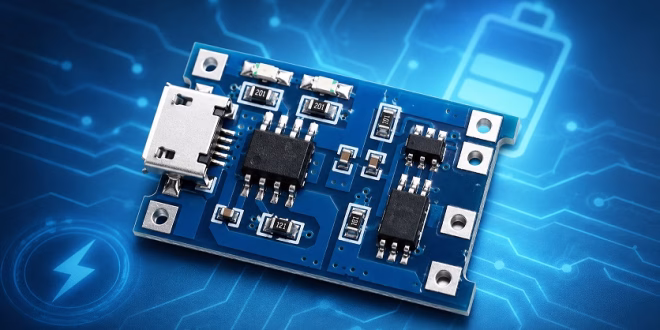
The TP4056 charging module is a small lithium battery charger board based on the TP4056 IC. The TP4056 is a linear charger designed for one single-cell lithium-ion battery. It charges the battery using a constant-current and constant-voltage charging method, often called CC/CV charging.
Most TP4056 modules include a USB connector, a TP4056 charger IC, charging indicator LEDs, and solder pads for the battery. Some versions also include a battery protection circuit. These protected modules usually have extra OUT+ and OUT− pads for powering a load.
A typical TP4056 module can be used with:
- 18650 lithium-ion cells
- Flat LiPo pouch cells
- Small single-cell rechargeable lithium battery packs
- Battery-powered Arduino projects
- ESP32 sensor nodes
- Portable microcontroller projects
However, the important phrase is single cell. The TP4056 is for one 3.7 V nominal lithium cell only. Do not use a TP4056 module to directly charge 2S, 3S, 7.4 V, 11.1 V, or other multi-cell battery packs.
TP4056 Module Versions
There are two common TP4056 module types.
The first type is the basic charger-only module. This board charges the battery, but it does not protect the battery from over-discharge, over-current, or short circuits. It usually has only IN+/IN− and B+/B− terminals.
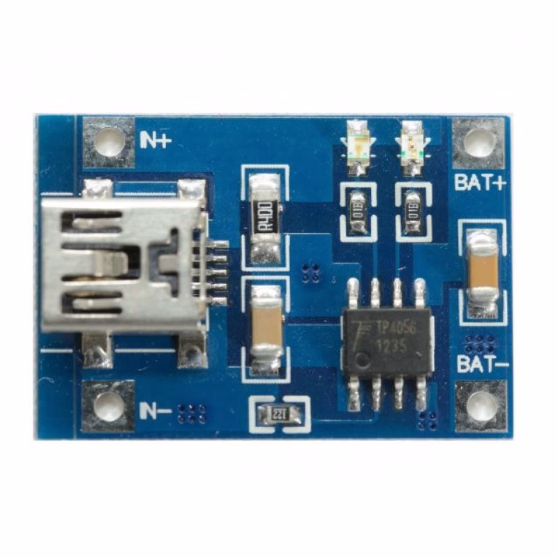
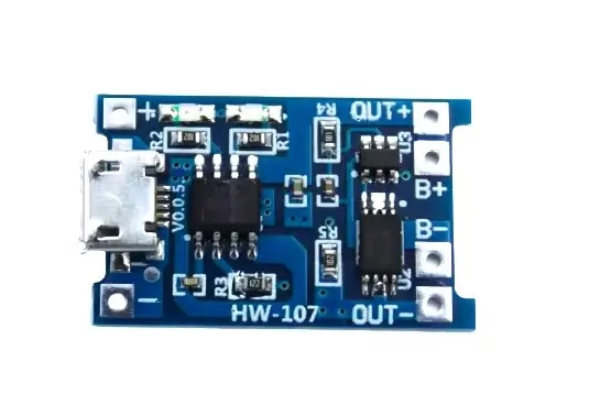
The second type is the TP4056 module with battery protection. This version usually includes the TP4056 charger IC plus a protection circuit, often using a DW01A protection IC and a dual MOSFET such as the FS8205A. It normally has B+/B− pads for the battery and OUT+/OUT− pads for the load.
For most hobby projects, the protected version is the better choice. The OUT+/OUT− pins make wiring easier, and the protection circuit adds a useful safety layer. Even so, you should still use good batteries, correct polarity, proper current limits, and safe charging practices.
TP4056 Module Pinout
The common TP4056 charging module with protection has six main solder pads:
| Pin | Function |
|---|---|
| IN+ / 5V | Positive 5 V charging input |
| IN− / GND | Charging input ground |
| B+ | Battery positive terminal |
| B− | Battery negative terminal |
| OUT+ | Positive output for the load |
| OUT− | Negative output for the load |
Some modules use slightly different labels. For example, IN+ may be labeled 5V, USB+, or VIN+. OUT+ may be labeled P+, Load+, or VOUT+. OUT− may be labeled P−, Load−, or VOUT−.
The actual function is the same: input pins receive 5 V, battery pins connect to the lithium cell, and output pins connect to the project load.
TP4056 Pin Functions
IN+ or 5V
The IN+ pin is the positive charging input. Connect this pin to a regulated 5 V supply. On many modules, this is already connected to the onboard Micro USB or USB-C connector. You can power the module from a USB charger, USB port, or a regulated 5 V supply. Avoid using an unstable or high-voltage source. Although the TP4056 IC has a higher absolute maximum input rating, practical TP4056 modules are normally intended for 5 V operation.
IN− or GND
The IN− pin is the charging input ground. Connect it to the ground of your 5 V charging supply.
B+
The B+ pin connects to the positive terminal of the lithium battery. This should be one single 3.7 V nominal Li-ion or LiPo cell.
B−
The B− pin connects to the negative terminal of the lithium battery. Be careful with polarity. Reversing the battery connection can damage the module, the battery, or both.
OUT+
The OUT+ pin is the positive load output on protected TP4056 modules. This pin provides battery voltage, not regulated 5 V. When the battery is full, OUT+ may be close to 4.2 V. As the battery discharges, the voltage drops. Therefore, you should not assume that OUT+ is a stable 5 V output.
OUT−
The OUT− pin is the negative load output. On protected modules, OUT− may pass through the protection circuit. Because of this, you should connect your load to OUT+ and OUT− instead of connecting directly to B+ and B−.
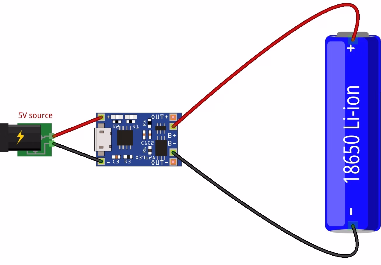
Basic TP4056 Wiring
The simplest TP4056 wiring uses only a battery and a USB input. Connect the battery positive wire to B+. Connect the battery negative wire to B−. Then power the module through its USB connector or through IN+ and IN−.
Basic charging connection:
| TP4056 Module | Battery |
|---|---|
| B+ | Battery positive |
| B− | Battery negative |
If you are using the module only as a charger, this is enough. The onboard LED will usually show the charging status.
On many modules, a red LED means the battery is charging. A blue or green LED means the battery is fully charged or in standby. However, LED colors can vary depending on the module manufacturer.
TP4056 Wiring with a Load
If your module has OUT+ and OUT− pins, connect your project load to these output pins.
| TP4056 Module | Project Load |
|---|---|
| OUT+ | Positive input of your circuit |
| OUT− | Ground of your circuit |
For example, if you are powering a MT3068 boost converter, connect OUT+ to the boost converter input positive pin and OUT− to the boost converter input negative pin. Then use the regulated output of the boost converter to power your Arduino or other 5 V device.
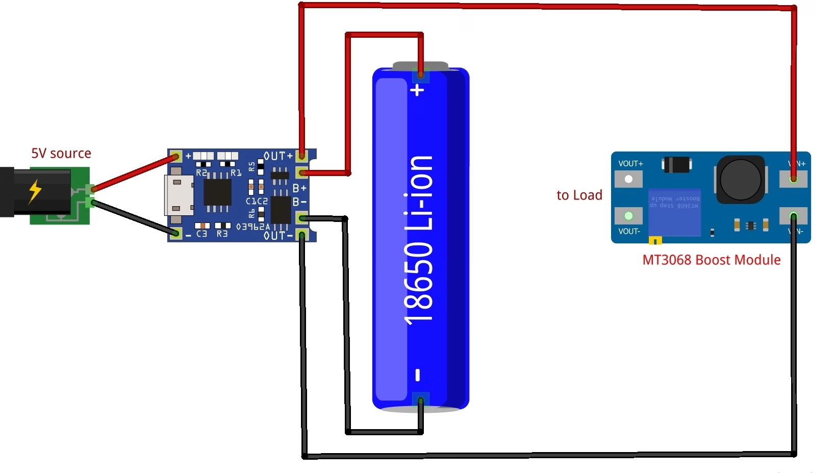
This is the better arrangement:
TP4056 OUT+ → Boost Converter IN+
TP4056 OUT− → Boost Converter IN−
Boost Converter 5V OUT → Arduino 5V
Boost Converter GND → Arduino GND
This way, the Arduino receives a stable 5 V supply instead of the changing battery voltage. Do not connect the boost converter to the Arduino until you have adjusted its output to 5.0 V. Many MT3608 modules are adjustable and may output a higher voltage if the trimmer is set incorrectly.
Is OUT+ a 5 V Output?
No. This is one of the most common TP4056 mistakes. The OUT+ pin is not a regulated 5 V output. It is usually connected to the battery through the protection circuit. That means its voltage follows the battery voltage. A single lithium cell is about 4.2 V when fully charged. During use, its voltage drops. The nominal voltage is usually 3.7 V, but the actual voltage depends on the charge level. Because of this, you need a voltage converter or regulator if your project requires a fixed voltage. Use a boost converter if your project needs 5 V. Use a 3.3 V regulator or buck-boost converter if your project needs a stable 3.3 V supply.
Can You Use TP4056 with Arduino?
Yes, but the correct wiring depends on the Arduino board. An Arduino Uno or 5 V Arduino Nano should not be powered directly from OUT+ and OUT−. The battery voltage is too low for a stable 5 V board, and it is not high enough for the barrel jack or VIN pin either.
For an Arduino Uno, use this setup:
TP4056 module → 3.7 V lithium battery → 5 V boost converter → Arduino 5V pin
A 3.3 V Arduino Pro Mini can sometimes run from a lithium cell, depending on the board and clock speed. However, a proper 3.3 V regulator or buck-boost converter is still better if you need stable operation. For ESP32 boards, do not assume that the TP4056 output can directly power the 3.3 V pin. ESP32 boards can draw high current bursts when Wi-Fi is active. Use a regulator or power circuit that can supply enough current. Many ESP32 development boards are better powered through their 5 V/VIN pin using a boost converter, or through the 3.3 V pin using a strong regulated 3.3 V supply.
TP4056 with ESP32
The ESP32 is a popular match for battery-powered projects, but it is also more demanding than many simple Arduino boards. Wi-Fi and Bluetooth current spikes can cause resets if the power supply is weak.
For a battery-powered ESP32 project, the usual setup is:
TP4056 OUT+ → Boost converter or 3.3 V regulator
TP4056 OUT− → Regulator ground
Regulator output → ESP32 power input
If your ESP32 board has a 5 V input pin, you can use a boost converter set to 5 V. If you are powering the ESP32 directly through the 3.3 V pin, use a stable 3.3 V regulator that can handle the board’s peak current.
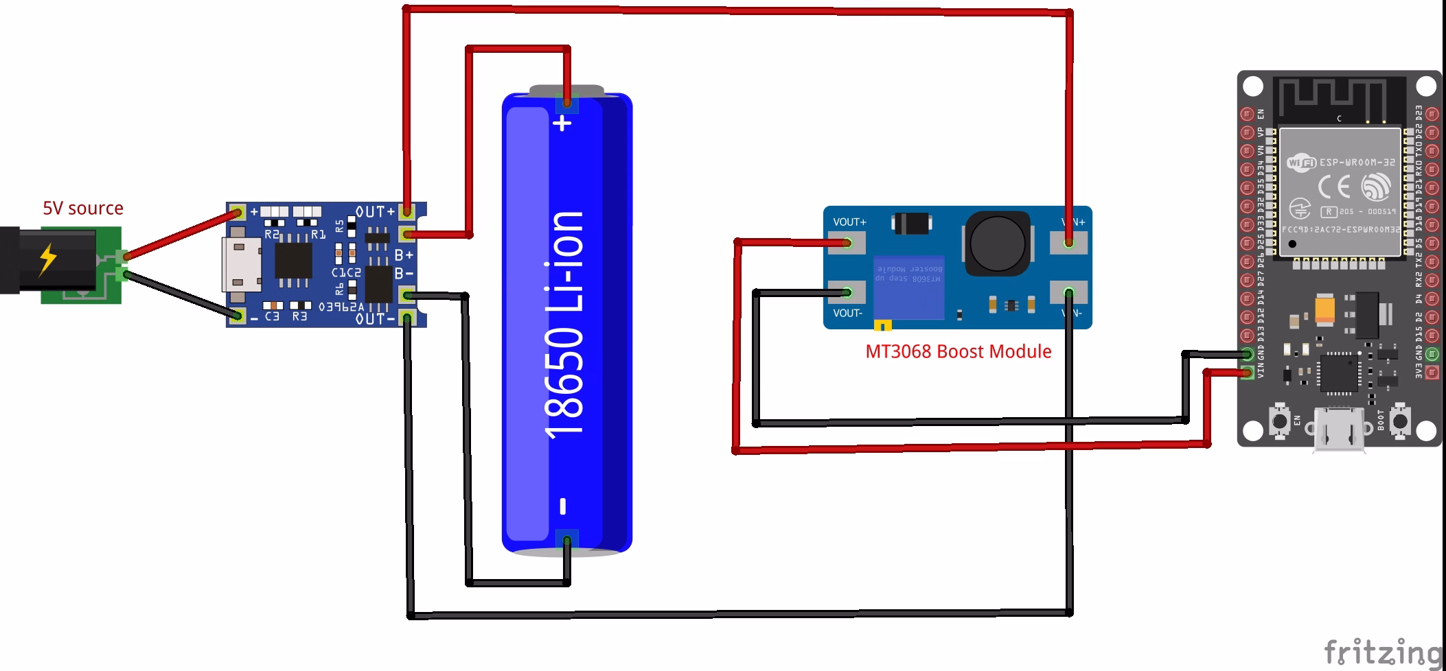
The example diagram above uses a MT3068 boost module. Again, do not connect the boost converter to the ESP32 VIN pin until you have adjusted its output to 5.0 V. Also add a capacitor near the ESP32 power input if the board resets when Wi-Fi starts. A capacitor cannot fix an underpowered regulator, but it can help with short current bursts.
TP4056 Charging Current
Many TP4056 modules are configured for a charge current of about 1 A. This is fine for many 18650 cells, but it may be too high for small LiPo batteries. The TP4056 charge current is set by a resistor connected to the PROG pin. On module boards, this resistor is usually a small SMD resistor near the IC.
Common TP4056 charge-current resistor values:
| RPROG (kΩ) | IBAT (mA) |
|---|---|
| 10 | 130 |
| 5 | 250 |
| 4 | 300 |
| 3 | 400 |
| 2 | 580 |
| 1.66 | 690 |
| 1.5 | 780 |
| 1.33 | 900 |
| 1.2 | 1000 |
The exact value can vary slightly, but this table is useful for choosing a safer charging current. As a rule, check the battery datasheet or label for the recommended charge current. For small LiPo cells, 1 A may be too much. For example, a 500 mAh LiPo battery should usually not be charged at 1 A unless the battery manufacturer specifically allows it. When in doubt, choose a lower charge current. Lower charging current produces less heat and is gentler on the battery.
How to Change TP4056 Charging Current
To change the TP4056 charging current, replace the PROG resistor with a different value.
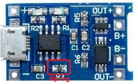
For example, many modules use a 1.2 kΩ resistor for about 1 A charging. If you replace it with a 2 kΩ resistor, the charge current drops to around 580 mA. If you replace it with a 4.7 kΩ resistor, the charge current drops to around 250 mA. This is useful when charging smaller batteries.
Before changing the resistor, disconnect the battery and USB input. Use a fine-tip soldering iron and work carefully because the resistor is usually very small.
TP4056 Charging Stages
| Charge state | Red LED / CHRG | Green LED / STDBY |
|---|---|---|
| Charging | Bright | Extinguish |
| Charge termination | Extinguish | Bright |
| VIN too low; battery temperature too low or too high; no battery | Extinguish | Extinguish |
| BAT pin connected to 10 µF capacitor; no battery | Green LED bright; red LED coruscates every 1–4 s | Green LED bright; red LED coruscates every 1–4 s |
The TP4056 charges a lithium battery using a CC/CV charging process. First, the charger supplies a constant current to the battery. During this stage, the battery voltage rises. When the battery reaches about 4.2 V, the charger switches to constant-voltage mode. The voltage stays near 4.2 V while the charging current gradually decreases. Finally, the charger terminates the charge when the current drops to a low level. On many modules, the charging LED turns off, and the full/standby LED turns on. This charging method is suitable for single-cell lithium batteries, but only when the battery and charger are wired correctly.
TP4056 with Protection Circuit
A protected TP4056 module includes more than just the TP4056 charger IC. As shown in the protection circuit schematic below, the module also uses a separate battery protection section built around a DW01A protection IC and an FS8205A dual MOSFET.
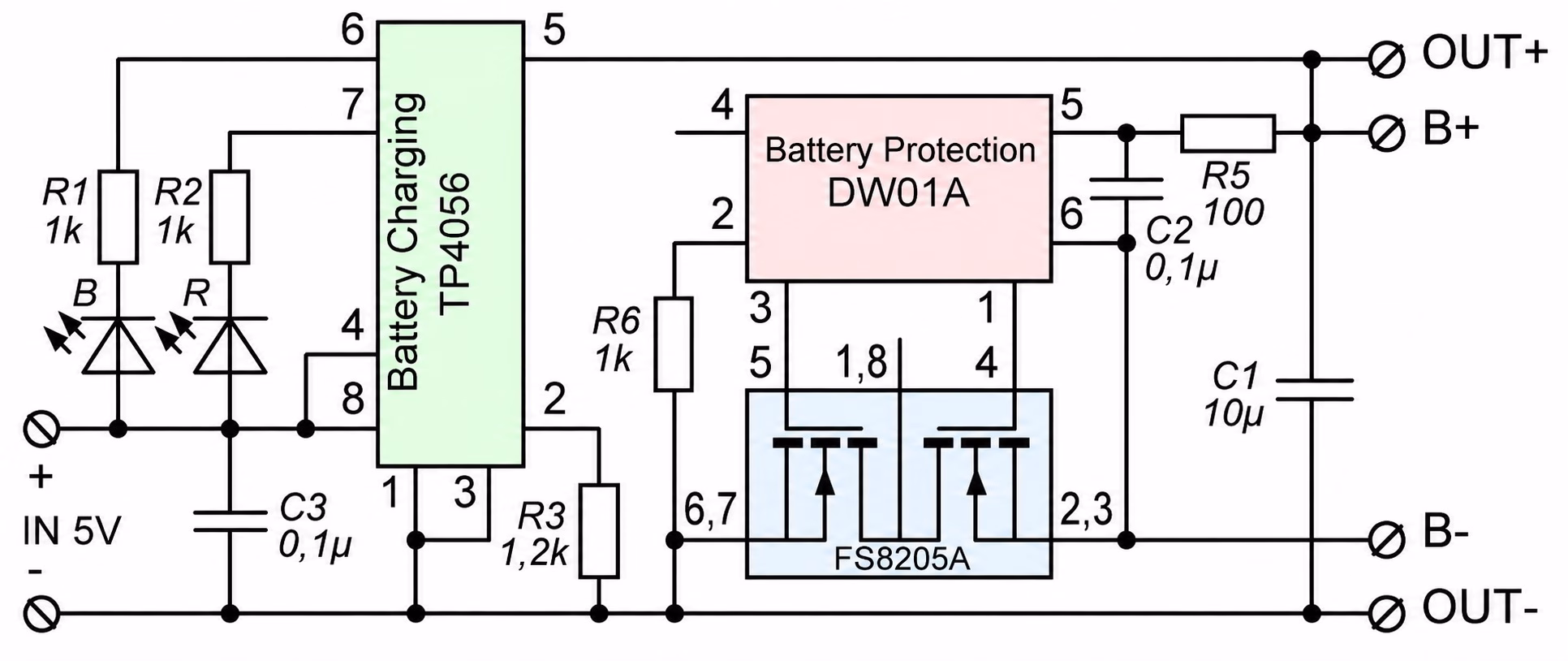
In this circuit, the TP4056 handles the actual charging process. It controls the charging current and charges the single lithium cell up to its full-charge voltage. Meanwhile, the DW01A and FS8205A section monitors and protects the battery during use.
The protection circuit can disconnect the battery or load during fault conditions such as:
- Battery over-discharge
- Battery overcharge
- Short circuit
- Excessive current
This is why protected TP4056 modules usually have separate B+ / B− and OUT+ / OUT− pads. The battery connects to B+ and B−, while the project load connects to OUT+ and OUT−. The protection MOSFETs sit between the battery and the output path, allowing the module to cut off the load when the battery voltage becomes too low or when a fault occurs.
However, the protection circuit does not turn the TP4056 module into a regulated power supply. The OUT+ pin still follows the battery voltage, so it can be around 4.2 V when fully charged and lower as the battery discharges. Therefore, use a boost converter if your project needs a stable 5 V output, or use a suitable regulator if your circuit needs 3.3 V.
Also, the protection circuit does not make every battery mistake safe. You still need to use the correct battery type, observe proper polarity, choose a suitable charging current, and avoid using the module with multi-cell battery packs.
TP4056 Without Protection
Some TP4056 modules do not include protection circuitry. These modules are smaller and may have only battery pads and input pads.

You can use a charger-only module if the battery already has its own protection circuit. Many flat LiPo battery packs include a small protection board under the wrapper. Some 18650 cells also come as protected cells. However, bare unprotected lithium cells should not be used carelessly. Over-discharging or shorting a lithium battery can be dangerous. If you are not sure, use a TP4056 module with protection and a battery from a reliable source.
Can the TP4056 Charge While Powering a Load?
A TP4056 module can be connected to a battery while a load is also connected, but this is not the same as proper power-path management. This is an important limitation. The TP4056 detects charge completion partly by monitoring the battery charging current. If your circuit is drawing current while the battery is charging, the module may not correctly detect when the battery is full. The load current can confuse the termination behavior. For small loads, many hobby circuits still appear to work. However, for reliable design, especially with ESP32 boards, motors, displays, or other changing loads, you should use a proper load-sharing or power-path circuit. A better design uses a circuit that powers the load from USB when USB is present, while also charging the battery separately. When USB is removed, the battery then powers the load.
Is the TP4056 a UPS Module?
No. A basic TP4056 module is not a complete UPS module. A UPS circuit needs power-path management. It must decide whether the load should be powered from USB input or from the battery. It should also switch cleanly between sources and charge the battery correctly. The TP4056 module only handles battery charging. Some protected modules also protect the battery. However, they do not provide ideal load sharing or automatic power-path control by themselves. If you need a true small UPS, use a charger module with power-path management, or add a proper load-sharing circuit.
Can You Use a Solar Panel with TP4056?
You can use a solar panel only if the TP4056 input receives a suitable regulated voltage. Do not connect a solar panel directly to the TP4056 input without checking the voltage and current behavior. Solar panels do not behave like stable USB power supplies. Their voltage changes with sunlight and load. A TP4056 module expects a stable 5 V input, so direct solar charging can be unreliable. For solar projects, use a solar lithium charger module or a solar charging circuit designed for variable panel input.
Can TP4056 Charge Two Batteries?
The TP4056 is designed for one lithium cell. You should not use one TP4056 module to directly charge a 2S battery pack. A 2S lithium pack needs a different charger and balancing circuit. You may connect cells in parallel only if you understand lithium battery safety, the cells are matched, and they are at the same voltage before connection. For beginners, the safer answer is simple: use one TP4056 module for one single-cell battery.
TP4056 for 18650 Batteries
The TP4056 module is commonly used with 18650 lithium-ion cells. A typical setup uses one 18650 cell connected to B+ and B−. For projects that need 5 V, add a boost converter after the TP4056 output. For projects that need 3.3 V, add a suitable regulator. Do not assume all 18650 cells are safe or high quality. Avoid old, damaged, dented, unknown, or fake cells. Also, make sure the charging current is suitable for the cell.
TP4056 for LiPo Batteries
The TP4056 can also charge single-cell LiPo batteries. Many small LiPo packs have a nominal voltage of 3.7 V and a full-charge voltage of 4.2 V, which matches the TP4056 charging profile. The main issue with small LiPo batteries is charging current. Many TP4056 modules default to around 1 A, which can be too high for small batteries. If you are using a 300 mAh, 500 mAh, or 800 mAh LiPo cell, consider changing the PROG resistor to reduce the charge current.
TP4056 Heat
The TP4056 is a linear charger. That means it dissipates excess voltage as heat. The heat depends on the input voltage, battery voltage, and charging current. If the input is 5 V and the battery is low, the voltage difference across the charger is larger. At high charge current, the module can become hot. Some warmth is normal. However, if the module becomes too hot to touch, reduce the charging current, improve airflow, or use a different charging solution. Using a lower input voltage close to 5 V, avoiding excessive charge current, and matching the current to the battery all help reduce heat.
Common TP4056 Problems
Red LED Stays On
A red LED usually means the battery is charging. If it stays on for a very long time, the battery may be large, deeply discharged, damaged, or the load may be drawing current while charging. Disconnect the load and check again. Also measure the battery voltage with a multimeter.
Blue or Green LED Never Turns On
The battery may not be reaching full charge. The charger may also fail to terminate if a load is connected while charging. Check the battery voltage. A fully charged lithium cell should be near 4.2 V. If it never gets close, check the battery, wiring, and input supply.
Module Gets Hot
The charge current may be too high, especially if you are charging a small battery. Replace the PROG resistor with a higher value to reduce the current. Also check your input voltage. Do not feed the module with a high-voltage supply.
Battery Does Not Charge
Check the battery polarity first. Then check the input voltage at IN+ and IN−. Make sure the USB cable is not power-only damaged or current-limited. Also check whether the battery voltage is extremely low. Some protection circuits disconnect deeply discharged batteries.
Project Resets When Running from Battery
The TP4056 does not regulate the output. If your Arduino, ESP32, or sensor resets, your regulator or boost converter may not be supplying enough current. Use a better regulator, add decoupling capacitors, and check the load current.
TP4056 Safety Tips
Lithium batteries store a lot of energy, so always treat them carefully.
Follow these safety tips:
- Use the TP4056 only with one 3.7 V lithium cell.
- Do not use it with 2S or 3S battery packs.
- Check battery polarity before connecting.
- Use a protected module or a protected battery.
- Set the charge current correctly for the battery.
- Do not charge damaged, swollen, or leaking batteries.
- Do not short the battery terminals.
- Do not leave experimental battery circuits unattended.
- Keep the battery away from flammable materials while testing.
- Use a fuse or protection circuit for larger battery-powered projects.
Example: TP4056 with Arduino Battery Monitor
One practical use for the TP4056 module is a rechargeable Arduino battery monitor. The battery connects to the TP4056 module, while the Arduino measures the battery voltage through a voltage divider.
A simple system can use:
- TP4056 charging module
- Single 18650 or LiPo battery
- Arduino Nano or Pro Mini
- Voltage divider
- Small LCD or OLED display
- Boost converter or regulator, depending on the Arduino board
The TP4056 handles charging, while the Arduino displays the battery voltage. This is useful for portable electronics, small robots, and field sensor projects. If the Arduino needs 5 V, place a boost converter between the TP4056 output and the Arduino. If you use a 3.3 V microcontroller, use a stable 3.3 V regulator.
TP4056 vs Boost Charger Modules
The TP4056 module charges the battery, but it does not boost the battery voltage. Some modules combine a lithium charger and a boost converter on one board. These are different from a basic TP4056 module. A charger-boost module may provide a regulated 5 V output from a lithium battery. Use a TP4056 module when you only need battery charging. Use a charger-boost module when you need both charging and a 5 V output. For more reliable battery-powered projects, especially those that must run while charging, look for modules with power-path management or load-sharing support.
Frequently Asked Questions
What battery can I use with TP4056?
Use one single-cell 3.7 V Li-ion or LiPo battery. The full-charge voltage should be 4.2 V.
Can I use TP4056 with a 12 V battery?
No. The TP4056 is not for 12 V lead-acid batteries or multi-cell lithium packs.
Can I connect TP4056 OUT+ directly to Arduino 5V?
Not recommended. OUT+ follows the battery voltage and is not regulated 5 V. Use a boost converter for 5 V Arduino boards.
Does TP4056 include battery protection?
The TP4056 IC itself is a charger, not a full protection system. Some modules include extra protection components. Check whether your module has OUT+ and OUT− pads and protection ICs.
Can I use TP4056 for ESP32?
Yes, but use a proper regulator or boost converter. ESP32 boards need a stable supply and can draw high current bursts during Wi-Fi operation.
Can I use TP4056 while the device is running?
You can connect a load, but a basic TP4056 module does not provide proper power-path management. For reliable operation while charging, use a load-sharing or power-path circuit.
Why is my TP4056 module hot?
The TP4056 is a linear charger, so it dissipates heat during charging. Reduce the charge current if the module gets too hot.
Can TP4056 charge LiFePO4 batteries?
No. Standard TP4056 modules charge to 4.2 V, while LiFePO4 cells need a different charge voltage. Use a charger designed for LiFePO4.
Conclusion
The TP4056 charging module is a simple and affordable way to add USB charging to single-cell lithium battery projects. It works well with 18650 cells, LiPo batteries, Arduino projects, ESP32 sensor nodes, and other portable electronics. However, you must use it correctly. The TP4056 is only for one lithium cell, and its output is not regulated 5 V. Also, a basic TP4056 module is not a complete UPS or power-path controller. For best results, use a protected TP4056 module, connect the battery to B+ and B−, connect the load to OUT+ and OUT−, choose a safe charging current, and add the correct regulator or boost converter for your project.


