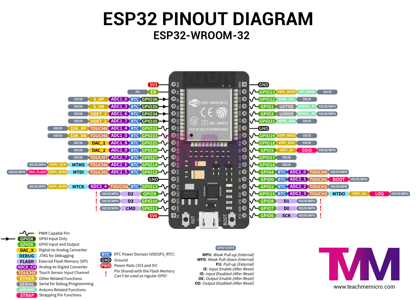
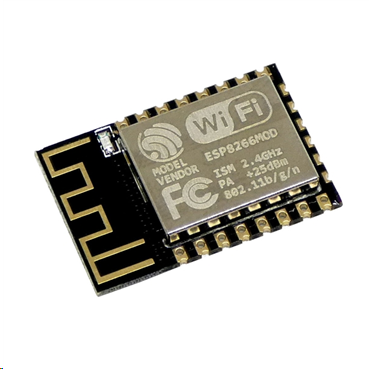
Adding an antenna to ESP32 can improve Wi-Fi and Bluetooth reliability when the board is installed far from an access point, placed inside an enclosure, or surrounded by components that interfere with its built-in PCB antenna. However, the modification involves more than soldering a piece of wire to the board.
The antenna connection is part of a carefully designed radio-frequency path. The antenna, connector, coaxial cable, PCB trace, matching components, and surrounding ground plane all affect how much of the ESP32's transmitted power is actually radiated.
In this tutorial, we will look at the safest ways of adding an external antenna to an ESP32. This includes choosing a module with a factory-installed U.FL connector, changing an antenna selection jumper, modifying an existing PCB, selecting the correct antenna, and positioning it inside the finished project.
Important: The antenna arrangement differs between ESP32 boards. Before moving or removing any component, find the schematic for your exact development board and inspect the RF section under magnification.
Why Add an External Antenna to an ESP32?
Most ESP32 development boards already contain a small meandered PCB antenna. For a board sitting openly on a desk, this antenna is often sufficient. Problems usually appear after the board is installed in the final product.
An external antenna may be useful when:
- The ESP32 is installed inside a metal enclosure.
- A battery, LCD, motor, relay, or large PCB is close to the built-in antenna.
- The device must communicate through several walls.
- The ESP32 is located near the edge of the access point's coverage.
- The product needs an antenna mounted outside its enclosure.
- The orientation of the built-in PCB antenna is unsuitable for the installation.
- A directional antenna is required for a fixed point-to-point link.
An external antenna does not automatically guarantee longer range. A badly positioned external antenna connected through a poor cable can perform worse than the original PCB antenna. The entire wireless link must be considered.
A simplified link budget can be written as:

Here, PR is the received power, PT is the transmitted power, GT and GR are antenna gains, and the remaining terms represent path, cable, and impedance mismatch losses.
This equation explains why installing a higher-gain antenna may not help when a long, lossy cable or an incorrectly modified RF trace introduces additional losses.
Understand Which Type of ESP32 Board You Have
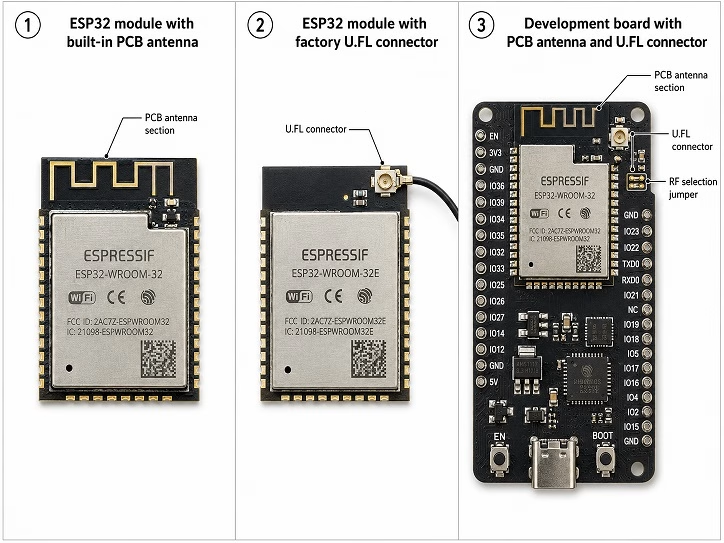
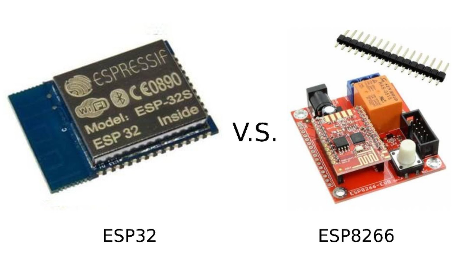
The term “ESP32 board” can refer to the ESP32 chip, a shielded ESP32 module, or a complete development board. The antenna may be part of any one of these assemblies.
| Board or Module Type | Antenna Arrangement | Recommended Approach |
|---|---|---|
| ESP32 module with PCB antenna | Antenna is etched directly onto the module PCB | Use the existing antenna or replace the module with an external-antenna version |
| ESP32 module ending in U or UE | Factory-installed micro-coaxial connector | Connect a compatible external antenna |
| Development board with PCB antenna and U.FL connector | A small RF jumper selects one antenna path | Move the jumper to the external-antenna position |
| Board with no connector but an accessible RF feed | Modification requires isolating the existing antenna | Attach a short 50 Ω micro-coaxial cable at the RF feed |
| Custom PCB using a bare ESP32 chip | RF matching and antenna network are designed on the PCB | Use controlled-impedance layout and RF validation |
ESP32 Modules with External Antenna Connectors
Espressif sells several module families in separate PCB-antenna and external-antenna versions. Examples include:
| PCB Antenna Version | External Antenna Version |
|---|---|
| ESP32-WROOM-32E | ESP32-WROOM-32UE |
| ESP32-S3-WROOM-1 | ESP32-S3-WROOM-1U |
| ESP32-C3-WROOM-02 | ESP32-C3-WROOM-02U |
The letter U commonly indicates an external-antenna connector in Espressif module names. However, this naming convention should not be assumed for every third-party board. Always verify the full module number printed on the metal shield.
A module such as the ESP32-WROOM-32UE does not contain the familiar meandered PCB antenna. Its RF output is routed directly to the small connector on the module. This is normally the easiest and most reliable option for adding an external antenna.
What Is a U.FL Connector?
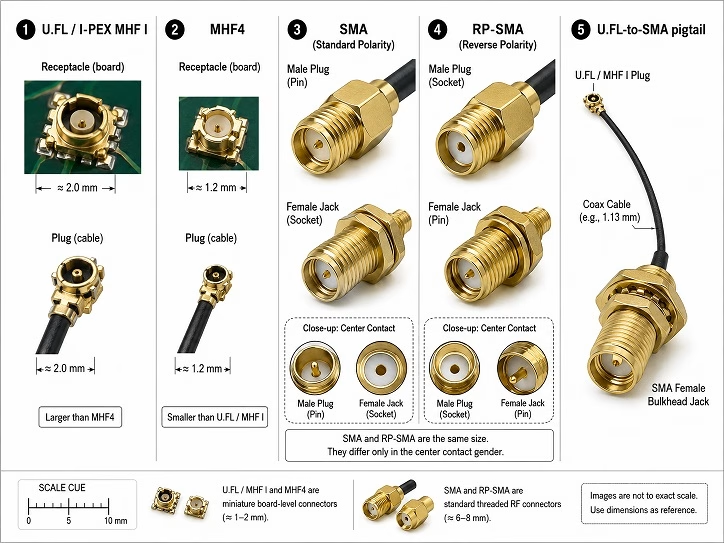
U.FL is a miniature 50 Ω coaxial connector family made by Hirose. ESP32 sellers sometimes call the same connector an IPEX connector. More precisely, Espressif's first-generation external antenna connector is compatible with Hirose U.FL, I-PEX MHF I, and Amphenol AMC cable plugs.
These connectors are very small and should be handled carefully. The cable plug must be centered directly over the board receptacle and pressed vertically downward. When correctly connected, it should produce a small tactile click.
Do not press the connector at an angle. Doing so can bend the center contact or pull the receptacle away from the PCB.
Also be careful when ordering cables. I-PEX MHF I and MHF 4 are different connector families. An MHF 4 cable is smaller and should not be forced onto a first-generation U.FL or MHF I receptacle.
U.FL-to-SMA Pigtails
A common arrangement uses a short U.FL-to-SMA coaxial pigtail. The U.FL end connects to the ESP32 module, while the SMA end is mounted through the enclosure. A larger external whip antenna then screws onto the SMA connector.
This arrangement provides two advantages:
- The fragile U.FL connector remains protected inside the enclosure.
- The external antenna can be replaced without repeatedly disconnecting the U.FL plug.
Choose the SMA end carefully. SMA and reverse-polarity SMA connectors look similar but have different center contacts. Verify that the panel connector and antenna are compatible before ordering.
Method 1: Use an ESP32 Module with a Factory U.FL Connector
The best method is to begin with a board or module designed for an external antenna. Examples include development boards populated with an ESP32-WROOM-32UE, ESP32-S3-WROOM-1U, or ESP32-C3-WROOM-02U.
Parts Required
- ESP32 development board with an external-antenna module
- Compatible U.FL or MHF I cable assembly
- 2.4 GHz, 50 Ω antenna suitable for the module
- Optional U.FL-to-SMA bulkhead pigtail
- Plastic connector tool or fine nonmetallic tweezers
Connection Procedure
- Disconnect USB power and any external power supply.
- Confirm the connector type using the module datasheet.
- Inspect the U.FL receptacle for contamination or damage.
- Align the cable plug directly over the receptacle.
- Press downward on the metal connector body rather than on the cable.
- Route the cable so that it does not pull sideways on the connector.
- Add strain relief to the cable several millimeters away from the receptacle.
- Install the antenna before applying power.
Do not attach adhesive, epoxy, or hot glue directly over the connector until the connection has been tested. Strain relief should hold the cable to the main PCB without pulling on the RF receptacle.
Method 2: Move the ESP32 Antenna Selection Jumper
Some development boards contain both a PCB antenna and a U.FL-style connector. Only one path should normally be active. A small zero-ohm resistor or solder bridge connects the ESP32's RF feed to the selected antenna.
This arrangement is particularly common on some ESP32 camera boards and compact IoT development boards.
How the Three-Pad Selector Works
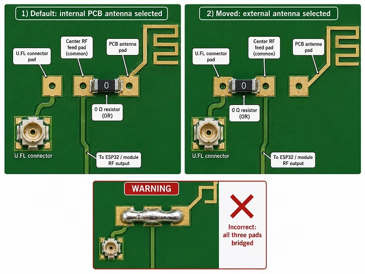
A typical selector contains three pads:
- The center pad is connected to the ESP32 RF output.
- One outside pad leads to the built-in PCB antenna.
- The other outside pad leads to the U.FL connector.
A zero-ohm resistor bridges the center pad to one of the two antenna paths. To select the external antenna, the resistor is removed from the PCB-antenna path and installed between the center pad and the connector path.
The arrangement is not identical on every board. The external path may be above, below, or beside the original jumper. Never assume that rotating the resistor by 90 degrees is correct without tracing the circuit.
Tools Required
- Fine-tip temperature-controlled soldering iron
- Fine soldering tweezers
- Flux
- Solder wick
- Magnification
- ESD-safe work surface
- Multimeter for checking shorts and continuity
Modification Procedure
- Remove all power from the board.
- Take a clear photograph of the original jumper position.
- Identify the radio feed, PCB antenna route, and connector route from the schematic or PCB traces.
- Apply a small amount of flux to the zero-ohm resistor.
- Heat both ends evenly and lift the component with tweezers.
- Clean the pads using solder wick if necessary.
- Place the resistor between the RF feed pad and the external-connector pad.
- Inspect the joint under magnification.
- Check that the PCB antenna path is no longer connected.
- Connect the external antenna before powering the ESP32.
A solder blob can sometimes be used instead of reinstalling the zero-ohm resistor, but it must not bridge all three pads. Connecting the PCB antenna and external antenna simultaneously creates an uncontrolled RF junction that can cause severe impedance mismatch.
A multimeter can identify an accidental short or open circuit, but it cannot prove that the RF path has a 50 Ω characteristic impedance at 2.4 GHz. Proper RF performance must be evaluated through signal, throughput, or network-analyzer testing.
Method 3: Add a Coaxial Connection to a Board Without U.FL
This is the most difficult method and should normally be used only for experimentation. If a standard ESP32-WROOM module already contains the PCB antenna, the RF path is part of the module itself. The carrier board does not usually provide a convenient antenna feed that can be modified.
For this type of board, replacing the complete module or development board with an external-antenna version is usually safer than cutting into the module's PCB antenna.
When a Direct PCB Modification Is Possible
A modification may be possible when:
- The RF feed trace is visible and accessible.
- The board contains an exposed matching network.
- The existing PCB antenna can be disconnected without disturbing the matching components.
- A nearby ground point is available for the coaxial shield.
- The modification is being performed on a prototype rather than a certified production product.
Why a Loose Wire Is Not Recommended
A common shortcut is to solder a random wire to the antenna feed. Although the wire may radiate some RF energy, it does not provide a controlled 50 Ω connection. The exposed section of wire, ground geometry, nearby objects, and solder joint all become part of the antenna.
The free-space wavelength at 2.4 GHz is approximately:

A free-space quarter wavelength is therefore approximately:

This does not mean that soldering a 31 mm wire to the ESP32 will produce a properly matched antenna. Practical antennas are affected by conductor width, ground plane dimensions, dielectric material, enclosure, loading, and nearby components.
Recommended Direct-Modification Approach
When a direct modification is unavoidable, use a short length of 50 Ω micro-coaxial cable rather than an unshielded wire.
- Locate the antenna feed and matching network.
- Determine which side of the series component is connected to the radio.
- Remove the jumper or cut the trace leading to the built-in antenna.
- Solder the coaxial cable's center conductor to the radio-side RF feed.
- Solder the coaxial shield to ground immediately beside the feed point.
- Keep the exposed center conductor extremely short.
- Secure the cable to the PCB so movement does not pull on the RF pad.
- Terminate the other end at a proper U.FL, SMA, or other 50 Ω connector.
The shield connection is as important as the center conductor. A long shield lead creates inductance and can make an otherwise short connection behave poorly at 2.4 GHz.
Do not scrape or cut the antenna trace while the board is powered. Avoid excessive heat because small RF pads can separate easily from the PCB.
Designing an External Antenna Connection on a Custom ESP32 PCB
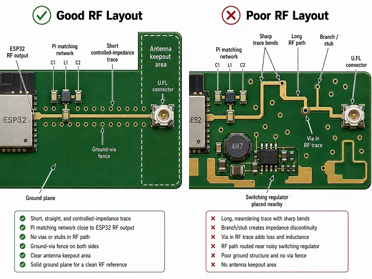
If you are creating a custom ESP32 board, the RF connection should be designed into the PCB rather than added afterward.
The RF trace between the matching network and antenna connector should have a characteristic impedance of approximately 50 Ω. The correct trace width depends on:
- PCB dielectric thickness
- Copper thickness
- Dielectric constant
- Distance to the reference ground plane
- Whether the trace is microstrip or coplanar waveguide
- Spacing between the trace and surrounding ground copper
Because these values depend on the PCB manufacturer's stack-up, copying the RF trace width from another board does not guarantee the correct impedance.
RF Layout Guidelines
- Keep the RF trace as short as possible.
- Do not create branches or stubs in the antenna path.
- Keep the trace width consistent.
- Avoid routing the RF trace through vias.
- Maintain a continuous ground reference beneath the trace.
- Use ground vias along the sides of a coplanar RF trace.
- Keep crystals, high-speed clocks, USB lines, UART lines, and switching regulators away from the antenna section.
- Place the matching network close to the ESP32 RF output or antenna as directed by the reference design.
- Keep copper and signal traces away from the connector area where required by the connector footprint.
- Include a pi or CLC matching footprint even when the initial design uses zero-ohm or unpopulated components.
The matching network gives you a way to compensate for the final PCB, connector, enclosure, and antenna during RF testing. The correct matching values normally require a vector network analyzer or equivalent RF measurement setup.
Choosing the Correct ESP32 External Antenna
The antenna must match the radio, connector, installation, and certification requirements of the exact ESP32 module.
Frequency
Common ESP32, ESP32-C3, and ESP32-S3 modules operate their Wi-Fi and Bluetooth radios in the 2.4 GHz band. A 2.4 GHz Wi-Fi or Wi-Fi/Bluetooth antenna is therefore required for these modules.
Do not select an antenna only because it physically fits the connector. An antenna intended only for GPS, cellular, LoRa, or sub-GHz operation may have very poor performance at 2.4 GHz.
For newer ESP32 variants supporting additional radio bands, use an antenna specified for every band that the design will use.
Impedance
The antenna and cable should have a nominal impedance of 50 Ω. This matches the RF system used by the ESP32 module and standard Wi-Fi antenna assemblies.
Antenna Gain
Higher gain does not mean that the antenna generates additional power. It concentrates radiation in particular directions while reducing it in others.
For example, a vertical high-gain whip may provide more horizontal coverage but create weaker areas directly above or below the antenna. A low-gain antenna may produce a more useful radiation pattern for a device whose orientation changes.
Certification must also be considered. Some Espressif external-antenna module datasheets specify the antenna used during certification and recommend that replacement antenna gain not exceed that value. The ESP32-WROOM-32UE and ESP32-S3-WROOM-1U documentation, for example, specifies a 2.4 GHz, 50 Ω antenna and lists 2.33 dBi as the certification antenna's maximum gain.
That value should not automatically be applied to every ESP32 module. Check the datasheet and certification documents for your exact part number. Using a different antenna type or higher gain may require additional EMC or regulatory testing.
External Whip Antenna
A screw-on whip antenna is useful when the antenna can be mounted outside the enclosure. It is easy to replace and can be oriented after installation.
Adhesive FPC Antenna
An adhesive flexible antenna can be installed inside a plastic enclosure. It should be mounted according to the antenna manufacturer's instructions. Some flexible antennas are designed to operate against a specific ground plane, while others require clearance from metal.
Do not fold, cut, or sharply bend the active antenna section. The coaxial cable may usually be routed around the enclosure, but the radiating element should remain in its intended shape.
PCB Antenna
A separate PCB antenna can be connected through a coaxial cable and mounted away from the ESP32 board. As with an FPC antenna, the antenna's ground-plane and clearance requirements must be followed.
Directional Antenna
A patch, panel, or Yagi-style antenna may be useful for a fixed point-to-point connection. It must be aimed correctly and may not be suitable for devices that move or need coverage in several directions.
ESP32 Antenna Placement
Antenna placement is often more important than antenna gain. Moving an ordinary antenna away from metal and electrical noise can produce a greater improvement than replacing it with a higher-gain antenna in the same poor location.
Keep the Antenna Away from Metal
Metal close to an antenna can block radiation and change its resonant frequency. Avoid placing the antenna directly against:
- Metal enclosures
- Large batteries
- Heat sinks
- LCD frames
- Metal mounting plates
- Large connectors
- Shielding cans
When using a metal enclosure, mount the antenna outside through a bulkhead connector. The coaxial cable can pass through the wall while the antenna remains in free space.
Keep the Antenna Away from Noise Sources
Switching regulators, DC motors, relays, high-speed displays, USB circuits, memory buses, and digital clocks can introduce interference. Place the antenna and its cable away from these circuits whenever possible.
Do not route the antenna cable parallel to high-current motor or relay wiring. If the paths must cross, crossing at approximately 90 degrees is generally preferable to running them together.
Respect the PCB Antenna Keepout Area
When using an ESP32 module's built-in PCB antenna, place the antenna end at the edge of the carrier PCB. Allowing the antenna to extend beyond the edge is usually the preferred arrangement.
If the antenna cannot extend past the board, there should be no copper, traces, or components under or beside the active antenna region. Espressif recommends providing at least 15 mm of clearance around the PCB antenna inside the finished enclosure.
The exact keepout geometry should come from the hardware design guide for the selected module.
Consider Polarization
A straight whip antenna normally has linear polarization. For communication with a typical access point whose antennas are vertical, starting with the ESP32 antenna vertically oriented is reasonable.
Rotating one antenna by 90 degrees relative to the other can reduce the received signal. Reflections inside buildings may reduce or change this effect, so the final orientation should still be tested experimentally.
Do Not Coil the Cable Around the Antenna
Extra coaxial cable should be routed away from the radiating element. Do not wrap it tightly around the whip or place a coil directly behind an adhesive antenna. The cable shield and nearby conductive objects can alter the antenna pattern.
Test the Finished Enclosure
An antenna that performs well on an open workbench may behave differently after the enclosure, battery, display, and wiring are installed. Always evaluate the complete assembled product.
Testing the ESP32 Antenna Modification
Test the original antenna before making the modification so that you have a baseline. Use the same ESP32 board, access point, location, power supply, orientation, and firmware for both tests.
Useful measurements include:
- Average RSSI
- Packet loss
- Connection and reconnection time
- TCP or UDP throughput
- Maximum usable distance
- Performance through walls
- Performance at different antenna orientations
RSSI is measured in dBm. Values closer to zero represent a stronger received signal. Because RSSI changes with movement, reflections, and nearby people, compare averages rather than relying on one reading.
Arduino RSSI Test Sketch
The following sketch connects to an access point and prints individual RSSI readings followed by their average:
#include <WiFi.h>

const char *ssid = "YOUR_WIFI_SSID";
const char *password = "YOUR_WIFI_PASSWORD";

const int sampleCount = 20;
const unsigned long sampleDelayMs = 500;

void setup() {
  Serial.begin(115200);
  delay(1000);

  WiFi.mode(WIFI_STA);
  WiFi.begin(ssid, password);

  Serial.print("Connecting");

  unsigned long startTime = millis();

  while (WiFi.status() != WL_CONNECTED) {
    delay(500);
    Serial.print(".");

    if (millis() - startTime > 30000) {
      Serial.println("\nConnection timed out.");
      return;
    }
  }

  Serial.println("\nConnected.");
  Serial.print("IP address: ");
  Serial.println(WiFi.localIP());
  Serial.print("BSSID: ");
  Serial.println(WiFi.BSSIDstr());
}

void loop() {
  if (WiFi.status() != WL_CONNECTED) {
    Serial.println("Wi-Fi disconnected.");
    delay(2000);
    return;
  }

  long rssiTotal = 0;

  Serial.println("Collecting RSSI samples:");

  for (int i = 0; i < sampleCount; i++) {
    int32_t rssi = WiFi.RSSI();
    rssiTotal += rssi;

    Serial.print("Sample ");
    Serial.print(i + 1);
    Serial.print(": ");
    Serial.print(rssi);
    Serial.println(" dBm");

    delay(sampleDelayMs);
  }

  float averageRssi = (float)rssiTotal / sampleCount;

  Serial.print("Average RSSI: ");
  Serial.print(averageRssi, 1);
  Serial.println(" dBm\n");

  delay(3000);
}
Record several test runs with the original antenna and several more with the external antenna. Do not hold the board or antenna during one test and place it on a table during another. Your hand can affect the antenna and invalidate the comparison.
Use More Than RSSI
An improved RSSI reading does not always mean that the entire connection is better. Interference, packet retries, antenna pattern, and access-point behavior can affect actual data transfer.
For a more useful evaluation, transfer a large file or run a local TCP throughput test while monitoring packet loss and disconnections. Repeat the test in the location where the device will actually operate.
Troubleshooting an ESP32 External Antenna
The External Antenna Performs Worse
Check the following:
- The zero-ohm jumper may still select the PCB antenna.
- Both antenna paths may accidentally be connected.
- The U.FL plug may not be fully seated.
- The antenna may be designed for the wrong frequency.
- The antenna may be too close to metal.
- The coaxial cable may be damaged or excessively long.
- The antenna may have a null in the direction of the access point.
- The connector or RF pad may have been damaged during soldering.
Wi-Fi Works Only When the Board Is Close to the Router
This often indicates an open or badly mismatched antenna path. Inspect the selector resistor and U.FL connection. Confirm that the antenna is connected to the radio side of the matching network rather than to the isolated PCB-antenna side.
The Signal Changes When the Cable Is Touched
A large change when touching the cable can indicate that the cable shield is not properly grounded, the connector is loose, or an exposed section of conductor is acting as part of the antenna.
The U.FL Connector Detached from the PCB
Do not attempt to glue it back in place and expect the RF path to work. The center signal pad and surrounding ground pads must be electrically restored. If the pads have lifted, repair normally requires microscope-assisted micro-soldering and a careful RF connection.
The Board Resets While Transmitting
This problem is more likely related to the power supply than the antenna. Wi-Fi transmission produces short current peaks. Check the 3.3 V regulator, USB cable, supply wiring, and decoupling capacitors.
Frequently Asked Questions
Can I connect an antenna directly to an ESP32 GPIO?
No. The Wi-Fi and Bluetooth antenna uses the ESP32's RF output path, not a general-purpose input/output pin. Connecting an antenna to a GPIO will not improve radio range and may expose that GPIO to unwanted RF signals or static discharge.
Can I use the PCB antenna and external antenna at the same time?
Not by simply connecting both paths together. A passive split creates an impedance mismatch and divides transmitted power. A proper diversity or dual-antenna design requires an RF switch, matching network, and support from the selected ESP32 variant and firmware.
Can I solder an SMA connector directly to the board?
Only when the board has a correctly designed 50 Ω RF footprint and sufficient mechanical support. A full-size SMA connector is too large to hang from a small antenna feed pad. A short micro-coaxial pigtail connected to a panel-mounted SMA connector is usually safer.
Will a 9 dBi antenna give three times the ESP32 range?
Not necessarily. Gain is directional, cable loss reduces the improvement, and the other end of the connection must still receive and return data. Higher gain may also exceed the antenna conditions used for the module's regulatory certification.
Does the external antenna improve both Wi-Fi and Bluetooth?
On common ESP32 modules, Wi-Fi and Bluetooth share the 2.4 GHz RF path. A correctly selected external antenna can therefore affect both. The exact internal radio arrangement should still be confirmed in the datasheet for the selected ESP32 variant.
Can I operate an external-antenna ESP32 without an antenna?
Avoid intentionally transmitting for extended periods without an antenna. An open connector produces a severe impedance mismatch, greatly reduces communication performance, and may stress the RF output stage.
Is firmware configuration required after moving the antenna jumper?
Normally, no. A passive zero-ohm antenna selector changes the physical RF path and is not controlled by software. Boards using an electronic RF switch or antenna-diversity circuit may require GPIO or ESP-IDF configuration.
Summary
The safest way of adding an external antenna to an ESP32 is to use a module designed for it, such as an ESP32-WROOM-32UE or ESP32-S3-WROOM-1U. The factory connector preserves the module's controlled RF path and avoids cutting the built-in PCB antenna.
For boards containing both a PCB antenna and a U.FL connector, locate the antenna selector and move its zero-ohm jumper to the external path. Do not leave both antenna paths connected.
Directly modifying a PCB-antenna module is possible in some cases, but it requires isolating the existing antenna and attaching a properly grounded 50 Ω micro-coaxial cable. A loose wire is not a reliable substitute for a matched antenna connection.
Finally, pay close attention to placement. Keep the antenna away from metal, high-speed circuits, batteries, displays, and noisy wiring. Test the complete device in its final enclosure using RSSI, packet loss, and actual throughput rather than assuming that a larger antenna will automatically provide better range.