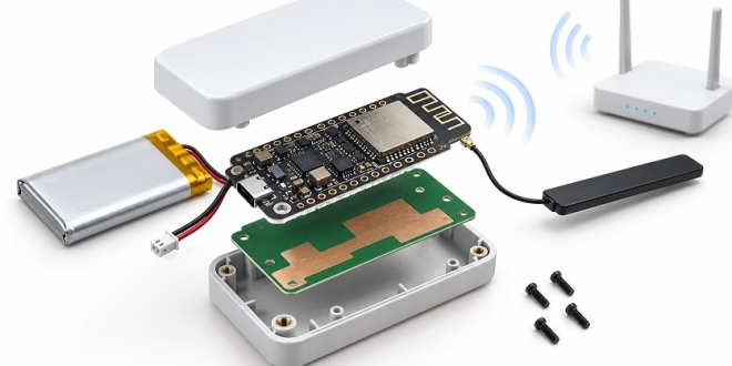
An embedded Wi-Fi device may work flawlessly on the development bench and begin dropping connections as soon as it is placed inside its production enclosure.
This is one of the most common challenges in embedded IoT development. A wireless module that performs well in an open laboratory environment can experience unstable connections after the battery, display, housing, cables, or mounting structure are introduced into the final product.
Reliable embedded Wi-Fi does not depend on the radio chip alone. The antenna, enclosure, RF layout, power system, firmware behavior, and network environment must work together as one system.
Replacing a wireless module with a newer or faster model rarely solves a product whose antenna is detuned by a battery, blocked by surrounding materials, affected by poor grounding, or supplied by an unstable power rail. The better approach is to protect link margin from the beginning: design the RF environment carefully, validate the final mechanical structure, and use repeatable measurements before making hardware changes.
The challenge is that an IoT device can appear stable during bench testing but fail at the edge of its expected coverage area. A USB cable, plastic housing, metal bracket, human hand, or production battery can change the RF characteristics significantly.
The goal of embedded Wi-Fi design is not achieving the highest peak throughput in a single test. It is maintaining a connection with enough margin to associate successfully, transfer data reliably, recover after an access point restart, and tolerate normal variation between production units.
Why an Embedded Wi-Fi Link Fails When the Radio Is Working
The Link Budget Depends on the Entire Product
.When engineers investigate Wi-Fi problems, the wireless module is often the first component they suspect. However, the radio IC is only one part of the complete communication path.
The received signal level at an IoT device depends on multiple factors, including:
- Transmit power
- Antenna efficiency and radiation pattern
- Antenna placement
- Path loss
- Polarization
- Nearby materials
- Receiver sensitivity
- Environmental interference
The antenna does not generate additional power. Instead, it determines how efficiently radio energy is transferred between the transceiver and the surrounding environment.
A poor antenna location can reduce the available link budget in both directions. Increasing the access point transmit power may improve the downlink connection, but the IoT device may still struggle to send data back because its own transmission path remains weak.
At 2.4 GHz, even small changes in the surrounding environment can affect antenna performance. Batteries, displays, shielding materials, USB cables, large ground planes, and wiring harnesses can change antenna tuning and radiation characteristics.
Therefore, the final production enclosure is the real test environment. A bare development board or evaluation kit can provide misleading results because it does not represent the completed product.
Bottom line:
A Wi-Fi reliability problem is usually a system-level margin problem rather than evidence that the radio IC itself is defective.
RSSI Alone Does Not Describe Wireless Reliability
RSSI (Received Signal Strength Indicator) is commonly used to evaluate wireless performance, but it only shows one part of the picture.
A strong RSSI value does not always mean a reliable connection. Two devices may report similar signal strength but perform differently because of:
- Channel interference
- Packet retries
- Network congestion
- Different modulation rates
- Poor antenna efficiency
- Packet loss
For example, an IoT device may show acceptable RSSI but repeatedly retransmit packets because of interference from nearby networks or Bluetooth devices.
A better evaluation method is to measure RSSI together with other indicators, such as:
- Connection success rate
- Association time
- Reconnect time
- Packet loss
- TCP throughput
- Negotiated PHY rate
- Retry rate
- Firmware disconnect logs
A reliable embedded Wi-Fi product is not defined by one signal-strength number. It is defined by stable communication under realistic operating conditions.
Why Antenna Design Determines Embedded Wi-Fi Reliability
The antenna is one of the most important components affecting embedded wireless performance. However, it is often underestimated because it appears to be a small part of the overall hardware design.
In reality, the antenna is part of the complete RF system. Its performance depends not only on the antenna shape but also on PCB size, ground structure, component placement, enclosure material, and installation environment.
Creating the Right RF Environment for the Antenna
A PCB antenna cannot simply be placed into any available area on the circuit board. It requires a carefully designed RF environment.
Engineers should follow the wireless module or antenna manufacturer's reference layout and maintain the recommended keep-out area. This region should remain free from copper, vias, batteries, metal components, shielding materials, and other objects that may affect antenna performance.
Even small mechanical changes can influence RF behavior. Moving a connector, changing the ground structure, or placing a battery close to the antenna area may shift antenna resonance and reduce communication reliability.
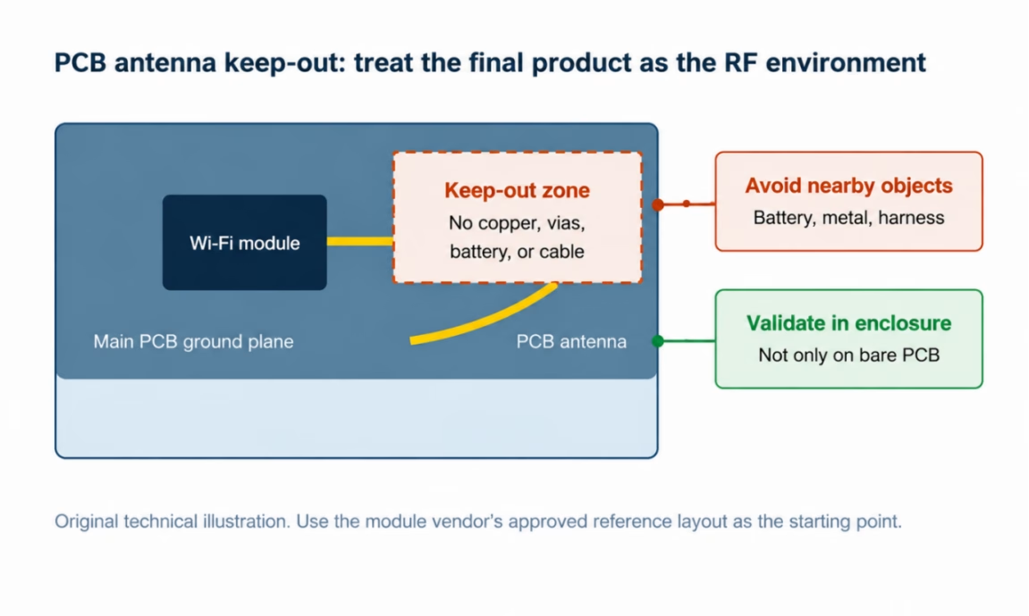
Figure 1. PCB antenna keep-out area and surrounding objects that affect RF performance
For designs using an external antenna or custom RF feed, the RF path should follow controlled 50-ohm transmission line principles. The feed should be kept short, unnecessary vias should be avoided, and the layout should follow the manufacturer's reference design.
For wireless modules with integrated PCB antennas, designers normally do not need to modify the antenna matching network. Instead, the priority is maintaining the approved host-board layout and ensuring that the final enclosure does not negatively affect RF performance.
For custom antenna designs, a matching-network footprint can provide flexibility during enclosure testing. However, it should be considered a tuning option rather than a replacement for correct antenna design.
For example, an ESP32 module may operate normally on an open development board but begin losing packets after a Li-ion battery is installed near the antenna. Moving the battery only a few millimeters away can change the antenna environment enough to improve performance.
Ground Design Is Part of the Antenna System
In many compact wireless products, the PCB ground plane is not only a return path for electrical signals but also an important part of the antenna system.
A small PCB size, split ground structure, or poorly designed return path can affect antenna efficiency and radiation performance. Removing ground near the antenna area may appear to create more space, but it can reduce performance if it does not follow the antenna reference design.
At the same time, noisy current paths from switching regulators, motors, relays, or other high-power components should be kept away from sensitive RF areas. Noise coupled into the RF path can reduce communication stability even when the antenna design itself is correct.
This is why copying an antenna layout from another product is often unreliable. The antenna shape alone does not determine performance. PCB thickness, dielectric material, ground structure, enclosure design, cable position, and installation environment all influence the final result.
The best approach is to start with the wireless module supplier's reference design and validate the complete product under real operating conditions.
PCB Antenna vs External Antenna: Choosing the Right Approach
Choosing between a PCB antenna and an external antenna depends on the product structure rather than simply comparing theoretical range performance.
A well-designed PCB antenna can provide reliable performance in a compact product, while an external antenna can solve mechanical limitations when the antenna cannot be placed in an ideal location.
PCB antennas suit compact and predictable products
A PCB antenna is often a practical choice for small IoT devices with a plastic enclosure, stable PCB layout, and predictable installation conditions.
Because the antenna is integrated directly into the circuit board, this approach removes additional connectors and coaxial cables. It reduces assembly complexity, eliminates cable loss, and can lower manufacturing cost.
PCB antennas are commonly used in products such as:
- Smart home devices
- Sensors
- Wearable equipment
- Compact gateways
- Consumer IoT products
However, PCB antennas require careful mechanical planning. Changes introduced late in development can affect wireless performance. For example, moving a battery closer to the antenna, adding a metal decorative component, or changing the enclosure material may alter antenna tuning and radiation characteristics.
PCB antennas are not inherently inferior to external antennas. Their performance depends on whether the product design provides a suitable RF environment.
External Antennas Provide Placement Flexibility
External antennas are useful when internal product constraints make antenna placement difficult.
Typical applications include:
- Industrial gateways
- Outdoor monitoring devices
- Embedded computers
- Equipment installed inside metal cabinets
- Products with complex internal structures
An external antenna allows the radiating element to be positioned away from interference sources or blocking materials. This can improve installation flexibility and create more consistent wireless performance across different deployments.
However, an external antenna does not automatically guarantee longer range. The complete RF path must still be considered, including:
- Antenna quality
- Cable length
- Connector reliability
- Installation direction
- Antenna spacing
A long coaxial cable introduces signal loss, while poor connectors may create intermittent failures. For dual-stream Wi-Fi systems, antenna separation and orientation should also follow the module supplier's recommendations to maintain MIMO performance.
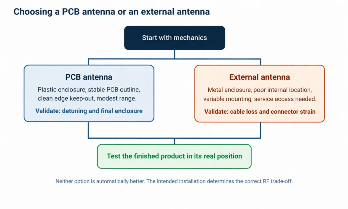
Figure 2. PCB antenna versus external antenna selection path
| Design choice | Best fit | Main strength | Main risk to validate |
|---|---|---|---|
| PCB antenna | Plastic enclosure, stable compact layout, modest range | Low cost and no cable loss | Detuning from ground, battery, housing, or hand effect |
| External antenna | Metal cabinet, flexible installation, difficult internal placement | Better physical placement and serviceability | Coax loss, connector reliability, installation variability |
| Pre-certified module with approved antenna | Faster integration path | Reference layout and known antenna options | Product enclosure can still change RF behavior |
When using a pre-certified wireless module, engineers should review certification documents before changing antenna type or gain. An unapproved antenna replacement may affect compliance requirements and require additional testing.
For Linux-based embedded systems, industrial gateways, and SBC platforms supporting PCIe, USB, or SDIO wireless interfaces, M.2 Wi-Fi modules can provide a modular approach to wireless connectivity.
When selecting an M.2 Wi-Fi module, engineers should evaluate:
- Host interface compatibility
- Supported Wi-Fi bands
- Driver support
- Antenna connector type
- Approved antenna configuration
A module with a higher advertised data rate does not always deliver better real-world performance if the antenna design, enclosure, or software support is unsuitable for the application.
The final decision should always include both board-level and enclosure-level RF validation.
What commonly degrades embedded Wi-Fi performance?
Even when antenna design is correct, other system-level factors can reduce embedded Wi-Fi reliability. In many cases, problems that appear to be RF issues are actually caused by power integrity, interference, or firmware behavior.
Power Integrity Can Cause Wireless Failures
Wi-Fi transmission requires short bursts of current, especially during network association and data transmission.
If the power supply cannot respond quickly enough, the module voltage may temporarily drop. These short voltage changes may cause:
- Unexpected resets
- Lost connections
- Driver errors
- Reduced transmission performance
A standard multimeter may not capture these short transient events. Engineers should measure the power rail at the wireless module using an oscilloscope during connection, transmission, and high-load operation.
Important factors to check include:
- Regulator transient response
- Local bulk capacitance
- High-frequency decoupling
- Ground return design
- Battery voltage under load
Power paths shared with motors, relays, LEDs, or switching converters can introduce noise into the wireless system. If a Wi-Fi problem occurs only when another component operates, checking power integrity should come before changing the antenna design.
Channel Conditions and Firmware Behavior Also Affect Reliability
Wireless performance is not determined only by hardware design. The surrounding network environment and firmware behavior can also influence connection stability.
At 2.4 GHz, interference from nearby access points, Bluetooth devices, wireless peripherals, and other equipment may reduce performance more than a small difference in antenna gain.
For this reason, wireless testing should be performed under realistic deployment conditions rather than only in a quiet laboratory environment. Engineers should evaluate the product using the expected Wi-Fi band, channel width, security settings, and network traffic conditions.
Firmware behavior is another important factor. A device may appear to have a wireless problem when the actual issue is related to connection management.
Common examples include:
- Poor reconnect strategies
- Incorrect power-saving behavior
- DHCP renewal issues
- Improper roaming decisions
- Weak error handling
A reliable IoT device should be able to identify connection failures, recover efficiently, and avoid excessive retries that consume power or create additional network load.
Before changing antenna hardware, engineers should confirm that power stability, interference conditions, and firmware behavior are not the actual causes of wireless instability.
How to Test Embedded Wi-Fi Reliability
Testing an embedded Wi-Fi product requires evaluating the complete device rather than only the wireless module.
A development board may perform well on a laboratory desk, but the final product can behave differently after adding the production enclosure, battery, cables, mounting structure, and other components.
The most important testing principle is simple: test the product in the same conditions where customers will actually use it.
Engineers should evaluate:
- Final enclosure design
- Production antenna placement
- Expected installation position
- Weak coverage locations
- Different network conditions
The goal is not only measuring maximum throughput. A reliable IoT device must maintain communication, reconnect after temporary interruptions, and continue performing its intended application tasks.
Useful measurements include:
- Connection success rate
- Reconnect time
- Packet loss
- Application throughput
- RSSI
- PHY rate
- Disconnect reasons
- Packet retry rate
RSSI alone cannot explain all wireless problems. A device may show acceptable signal strength while still suffering from interference, retransmissions, or unstable connections.
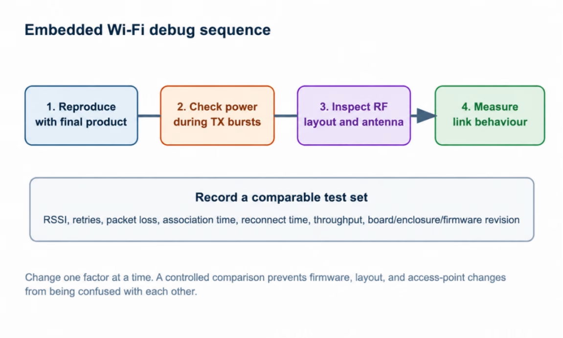 Figure 3. Embedded Wi-Fi debug sequence
When comparing different hardware or firmware versions, testing conditions should remain consistent. Engineers should keep the same access point, channel, bandwidth, security settings, physical location, and application traffic.
The antenna version, cable length, enclosure revision, battery condition, PCB version, and firmware version should also be recorded.
A repeatable test method turns unclear complaints such as “the Wi-Fi range is poor” into measurable engineering data.
Embedded Wi-Fi Troubleshooting Guide
| Symptom | Likely cause | First thing to check |
|---|---|---|
| Wi-Fi resets during transmission | Supply voltage droop | Probe the 3.3 V rail at the module |
| Works outside the enclosure but fails inside | Antenna detuning | Test battery, display, and enclosure placement |
| Good RSSI but poor throughput | Congestion or interference | Check channel use and packet retry rate |
| Random disconnects | Firmware or network state | Log disconnect reason codes and reconnect events |
| Range changes with orientation | Antenna radiation pattern | Test the final mounting position |
Embedded Wi-Fi Design Checklist
Before releasing an IoT device, engineers should verify the following key design points:
- Follow the wireless module or antenna supplier's recommended antenna layout and keep-out requirements.
- Validate performance with the final enclosure, battery, cables, and mounting structure installed.
- Ensure stable power delivery during Wi-Fi association, transmission bursts, and high-load operation.
- Evaluate wireless performance under realistic 2.4 GHz and 5 GHz deployment conditions.
- Monitor reconnect behavior, packet loss, retry rate, and application performance instead of relying only on RSSI.
- Keep antenna, cable, enclosure, firmware, and access point conditions consistent when comparing different revisions.
- Repeat wireless validation after any changes to the PCB, antenna, battery, cable, enclosure, or RF shielding.
A structured checklist helps engineering teams identify wireless problems earlier and reduces unexpected performance issues after product release.
Conclusion
Reliable Wi-Fi performance in embedded IoT products comes from protecting link margin throughout the entire design process.
The antenna should not be treated as an isolated component added at the end of development. Its performance depends on PCB layout, ground structure, enclosure design, power quality, firmware behavior, and installation environment.
A PCB antenna can provide excellent performance when the product can maintain a clean RF environment. An external antenna can provide additional flexibility when mechanical limitations make antenna placement difficult. However, both approaches require validation of the complete RF path.
The most successful embedded Wi-Fi designs are not necessarily those with the highest theoretical data rate. They are the products that maintain stable connections, recover quickly from interruptions, and perform consistently across real-world deployment conditions.
By combining careful RF design, stable power delivery, appropriate module selection, and repeatable testing, engineers can build embedded IoT devices with reliable wireless performance throughout their lifecycle.