A 16×2 character LCD is enough when you only need to display a few numbers or short messages. However, once your project needs icons, graphs, progress bars, larger fonts, or a proper user interface, a graphical LCD becomes a much better option. In this tutorial, I will show you how to interface a 128×64 graphical LCD with an Arduino Uno. The display used here is the common 12864 module based on the ST7920 LCD controller.
We will start by displaying text, then move on to drawing shapes, creating a simple sensor dashboard, and finally displaying a custom bitmap image.
Important: “128×64” only describes the screen resolution. There are other 128×64 displays based on controllers such as the KS0108, SSD1306, SH1106, and ST7565. The wiring and code in this tutorial are specifically for an ST7920-based LCD.
What Is a 128×64 Graphical LCD?
A 128×64 graphical LCD contains a grid of 128 horizontal pixels and 64 vertical pixels. Unlike a character LCD, its pixels can be individually controlled.
This gives us a total of:

Because the display is monochrome, each pixel normally requires only one bit. A complete screen image therefore, needs:

This is worth remembering when using an Arduino Uno. The Uno has only 2 KB of SRAM, so storing a full 1024-byte screen buffer consumes about half of its available RAM before we even include variables, library data, and other parts of the program.
To avoid running out of memory, we will use the page-buffer version of the U8g2 library.
ST7920 Interface Modes
The ST7920 supports three communication modes:
-
- 8-bit parallel
- 4-bit parallel
- Synchronous serial
Parallel mode is faster, but it requires many Arduino pins. Serial mode needs only three control signals, so it is usually the better choice for Arduino projects.
The PSB pin selects the interface:
-
- PSB connected to VCC: parallel mode
- PSB connected to GND: serial mode
In serial mode, the ST7920 uses its SID, SCLK, and CS signals. The controller’s serial interface is write-only and uses a slightly different data format from ordinary SPI devices, but the U8g2 library handles these details for us.
Components Required
For this tutorial, you will need:
- Arduino Uno or compatible board
- 128×64 ST7920 graphical LCD
- 10 kΩ potentiometer or trimmer
- 10 kΩ resistor for the LCD reset pull-up
- 100 Ω to 220 Ω resistor for the backlight
- Jumper wires
- Breadboard, optional
Some ST7920 modules already include an onboard contrast adjustment and backlight resistor. Check the PCB before adding external components.
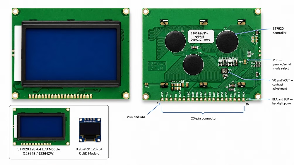
ST7920 128×64 LCD Pinout
The common ST7920 module has a 20-pin connector.
| Pin | Label | Function |
|---|---|---|
| 1 | GND or VSS | Ground |
| 2 | VCC or VDD | 5 V supply |
| 3 | VO | LCD contrast input |
| 4 | RS or CS | Chip select in serial mode |
| 5 | R/W or SID | Serial data input |
| 6 | E or SCLK | Serial clock |
| 7 | DB0 | Parallel data bit 0 |
| 8 | DB1 | Parallel data bit 1 |
| 9 | DB2 | Parallel data bit 2 |
| 10 | DB3 | Parallel data bit 3 |
| 11 | DB4 | Parallel data bit 4 |
| 12 | DB5 | Parallel data bit 5 |
| 13 | DB6 | Parallel data bit 6 |
| 14 | DB7 | Parallel data bit 7 |
| 15 | PSB | Parallel/serial mode selection |
| 16 | NC | Normally not connected |
| 17 | RST | LCD reset |
| 18 | VOUT | Contrast-voltage output |
| 19 | BLA or A | Backlight positive |
| 20 | BLK or K | Backlight negative |
Pins 7 through 14 are not needed when the LCD is operating in serial mode.
Module manufacturers sometimes change the functions or labels of pins 16 through 18. Always check the labels printed on your LCD PCB before applying power.
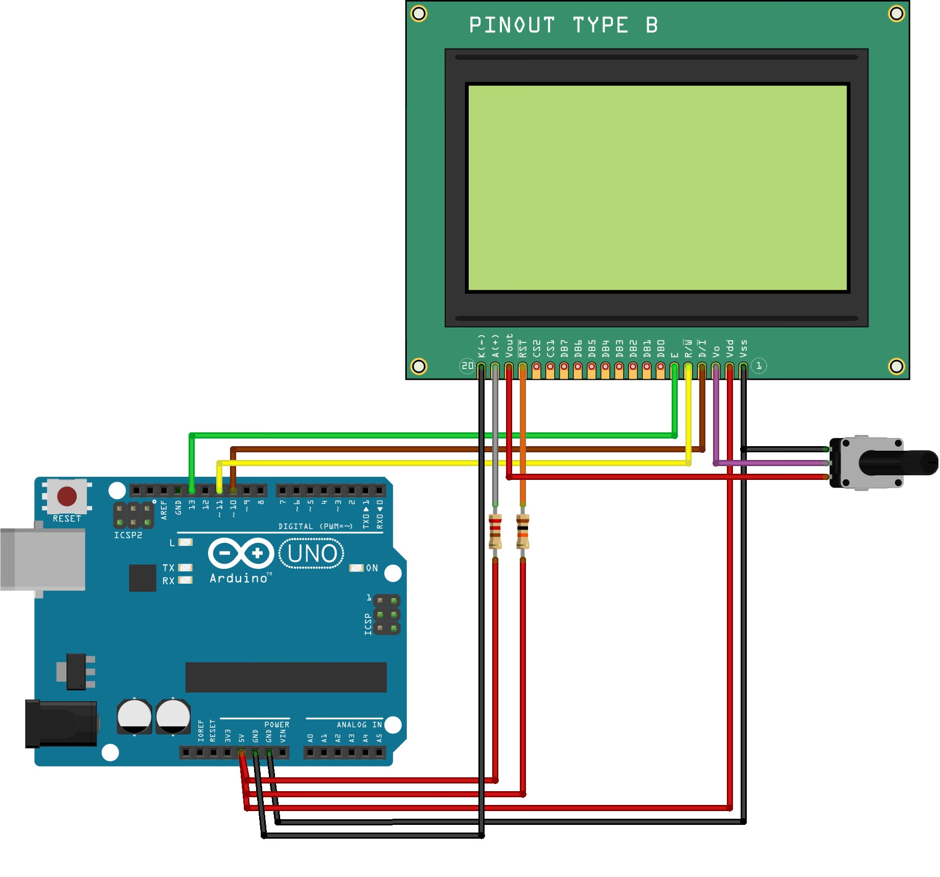
Arduino 128×64 LCD Wiring Diagram
We will connect the display using serial mode.
| ST7920 LCD | Arduino Uno | Purpose |
|---|---|---|
| GND | GND | Ground |
| VCC | 5V | LCD power |
| VO | Potentiometer wiper | Contrast |
| RS/CS | D10 | Chip select |
| R/W/SID | D11 | Serial data |
| E/SCLK | D13 | Serial clock |
| PSB | GND | Select serial mode |
| RST | 5V through 10 kΩ | Keep LCD out of reset |
| VOUT | One end of potentiometer | Contrast reference |
| BLA | 5V through 100–220 Ω | Backlight positive |
| BLK | GND | Backlight negative |
Connect the remaining end of the contrast potentiometer to GND. Its center pin or wiper connects to VO.
The contrast circuit will therefore look like this:
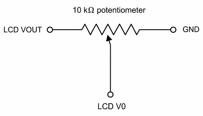
Slowly turn the potentiometer after powering the circuit. Incorrect contrast is one of the most common reasons an LCD appears completely blank even when the code and communication wiring are correct.
Why Use Pins 10, 11, and 13?
Pins 11 and 13 are the Arduino Uno’s normal MOSI and SCK pins. However, the first examples will use U8g2’s software-serial constructor, which lets us explicitly define the clock, data, and chip-select pins.
You can use different Arduino digital pins as long as you also update the constructor in the sketch.
Installing the U8g2 Library
We will use the U8g2 library to control the display. It supports the ST7920 and provides functions for displaying text, drawing shapes, and rendering bitmap images.
To install it:
- Open the Arduino IDE.
- Go to Sketch > Include Library > Manage Libraries.
- Search for U8g2.
- Install U8g2 by olikraus.
- Restart the Arduino IDE if the examples do not immediately appear.
The library provides separate constructors for different controllers, communication methods, and buffer sizes. For the ST7920, constructors beginning with U8G2_ST7920_128X64 are available for software SPI, hardware SPI, and parallel interfaces.
Arduino 128×64 LCD Hello World Code
Let us begin with a simple text example.
#include <Arduino.h>
#include <SPI.h>
#include <U8g2lib.h>

// ST7920 software serial connection:
// clock = D13
// data  = D11
// CS    = D10
//
// The LCD reset pin is connected to 5V through a pull-up,
// so U8X8_PIN_NONE is used for the reset argument.

U8G2_ST7920_128X64_1_SW_SPI u8g2(
  U8G2_R0,
  13,
  11,
  10,
  U8X8_PIN_NONE
);

void setup() {
  u8g2.begin();
}

void loop() {
  u8g2.firstPage();

  do {
    u8g2.setFont(u8g2_font_ncenB14_tr);

    u8g2.drawStr(5, 24, "Teach Me");
    u8g2.drawStr(20, 48, "Micro");

  } while (u8g2.nextPage());

  delay(1000);
}
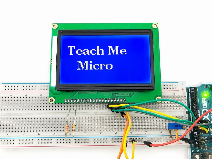
Upload the sketch to the Arduino. You should see two lines of text on the LCD.
How the Code Works
The first three lines include the required Arduino, SPI, and U8g2 headers:
#include <Arduino.h>
#include <SPI.h>
#include <U8g2lib.h>
The following statement creates the display object:
U8G2_ST7920_128X64_1_SW_SPI u8g2(
  U8G2_R0,
  13,
  11,
  10,
  U8X8_PIN_NONE
);
Let us break down the constructor name:
- U8G2 selects the full graphics API.
- ST7920 selects the display controller.
- 128X64 selects the display resolution.
- 1 selects a one-page display buffer.
- SW_SPI selects software-generated serial communication.
The constructor arguments are:
rotation, clock, data, chip_select, reset
U8G2_R0 means that the display uses its normal landscape orientation. U8g2 also provides U8G2_R1, U8G2_R2, and U8G2_R3 for rotating the display by 90, 180, and 270 degrees.
Initializing the Display
The display is initialized inside setup():
u8g2.begin();
This sends the required setup commands, clears the display, and takes it out of power-save mode.
Understanding the Picture Loop
Because we selected the page-buffer constructor, every drawing command must be placed inside the picture loop:
u8g2.firstPage();

do {
// Drawing commands go here
} while (u8g2.nextPage());
The library draws one section of the screen at a time. It then repeats the drawing code for the next section until the complete display has been updated.
The advantage is lower SRAM usage. The disadvantage is that every object on the screen must be redrawn during each page pass.
Selecting a Font
This line selects a font:
u8g2.setFont(u8g2_font_ncenB14_tr);
U8g2 includes many fonts, but larger fonts also consume more flash memory. For small status displays, compact fonts such as the following are useful:
u8g2_font_5x7_tr
u8g2_font_6x10_tr
u8g2_font_ncenB08_tr
u8g2_font_ncenB14_tr
Display Coordinates
The top-left corner of the screen is coordinate (0, 0).
The usable coordinate range is:
X: 0 to 127
Y: 0 to 63
The drawStr() Y coordinate represents the text baseline rather than the top of the letters. This is why placing text at Y coordinate zero normally cuts off most of the characters.
Using a Full Screen Buffer
On boards with more RAM, you can replace the page-buffer constructor:
U8G2_ST7920_128X64_1_SW_SPI
with the full-buffer constructor:
U8G2_ST7920_128X64_F_SW_SPI
You can then draw the display using:
u8g2.clearBuffer();

// Drawing commands

u8g2.sendBuffer();
The full buffer makes animation and screen updates easier, but a 128×64 monochrome image requires approximately 1024 bytes. The page-buffer version is generally safer for an Arduino Uno or Nano.
Drawing Shapes on the 128×64 LCD
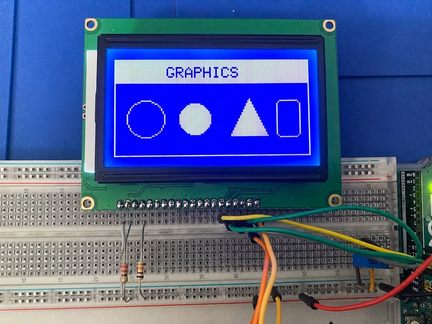
A graphical LCD is not limited to text. U8g2 includes functions for drawing lines, boxes, circles, triangles, frames, and individual pixels.
Here is a simple graphics demonstration:
#include <Arduino.h>
#include <SPI.h>
#include <U8g2lib.h>

U8G2_ST7920_128X64_1_SW_SPI u8g2(
  U8G2_R0,
  13,
  11,
  10,
  U8X8_PIN_NONE
);

void setup() {
  u8g2.begin();
}

void loop() {
  u8g2.firstPage();

  do {
    // Outer border
    u8g2.drawFrame(0, 0, 128, 64);

    // Header
    u8g2.drawBox(1, 1, 126, 15);
    u8g2.setDrawColor(0);
    u8g2.setFont(u8g2_font_6x10_tr);
    u8g2.drawStr(34, 12, "GRAPHICS");
    u8g2.setDrawColor(1);

    // Shapes
    u8g2.drawCircle(20, 39, 12);
    u8g2.drawDisc(52, 39, 10);
    u8g2.drawTriangle(75, 51, 88, 25, 101, 51);
    u8g2.drawRFrame(106, 27, 16, 25, 3);

  } while (u8g2.nextPage());

  delay(1000);
}
Some of the most useful drawing functions are:
| Function | Purpose |
|---|---|
| drawPixel(x, y) | Draws one pixel |
| drawLine(x1, y1, x2, y2) | Draws a line |
| drawHLine(x, y, width) | Draws a horizontal line |
| drawVLine(x, y, height) | Draws a vertical line |
| drawFrame(x, y, width, height) | Draws a rectangular outline |
| drawBox(x, y, width, height) | Draws a filled rectangle |
| drawCircle(x, y, radius) | Draws a circle outline |
| drawDisc(x, y, radius) | Draws a filled circle |
| drawTriangle(...) | Draws a triangle |
| drawRFrame(...) | Draws a rounded rectangular frame |
Creating a Simple Arduino Sensor Dashboard
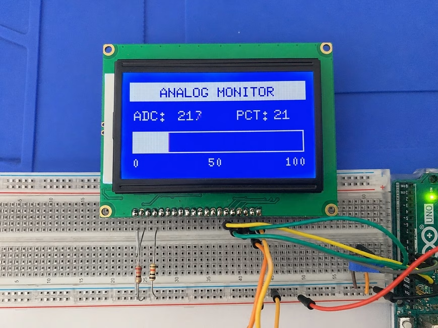
Now, let us create something closer to a real project. The following sketch reads an analog value from A0 and displays the reading as both a number and a bar graph.
You can connect the center pin of a 10 kΩ potentiometer to A0. Connect the other two potentiometer pins to 5V and GND.
#include <Arduino.h>
#include <SPI.h>
#include <U8g2lib.h>

U8G2_ST7920_128X64_1_SW_SPI u8g2(
  U8G2_R0,
  13,
  11,
  10,
  U8X8_PIN_NONE
);

const int sensorPin = A0;

void setup() {
  u8g2.begin();
}

void loop() {
  int sensorValue = analogRead(sensorPin);
  int percentage = map(sensorValue, 0, 1023, 0, 100);
  int barWidth = map(sensorValue, 0, 1023, 0, 122);

  u8g2.firstPage();

  do {
    // Header
    u8g2.drawBox(0, 0, 128, 14);
    u8g2.setDrawColor(0);
    u8g2.setFont(u8g2_font_6x10_tr);
    u8g2.drawStr(22, 11, "ANALOG MONITOR");
    u8g2.setDrawColor(1);

    // Raw ADC value
    u8g2.setFont(u8g2_font_6x10_tr);
    u8g2.drawStr(3, 28, "ADC:");

    u8g2.setCursor(35, 28);
    u8g2.print(sensorValue);

    // Percentage
    u8g2.drawStr(78, 28, "PCT:");

    u8g2.setCursor(105, 28);
    u8g2.print(percentage);

    // Bar graph
    u8g2.drawFrame(2, 36, 124, 16);

    if (barWidth > 0) {
      u8g2.drawBox(3, 37, barWidth, 14);
    }

    // Scale labels
    u8g2.setFont(u8g2_font_5x7_tr);
    u8g2.drawStr(2, 62, "0");
    u8g2.drawStr(57, 62, "50");
    u8g2.drawStr(112, 62, "100");

  } while (u8g2.nextPage());

  delay(100);
}
Notice that sensorValue, percentage, and barWidth are calculated before entering the picture loop. The values must remain unchanged while U8g2 is drawing all the display pages.
A similar screen could be used for:
- Temperature readings
- Battery-voltage monitoring
- Motor speed
- Tank level
- Pressure readings
- Light intensity
- Signal strength
- Servo position
Displaying a Bitmap Image
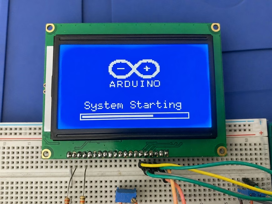
One of the main advantages of a graphical LCD is the ability to display logos, icons, symbols, and splash screens.
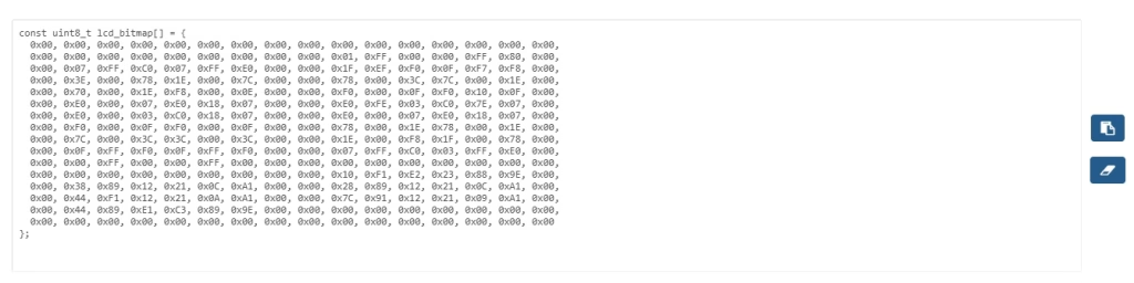
A bitmap image must first be converted into a C or C++ byte array. Manually creating a large byte array is possible, but it quickly becomes impractical.
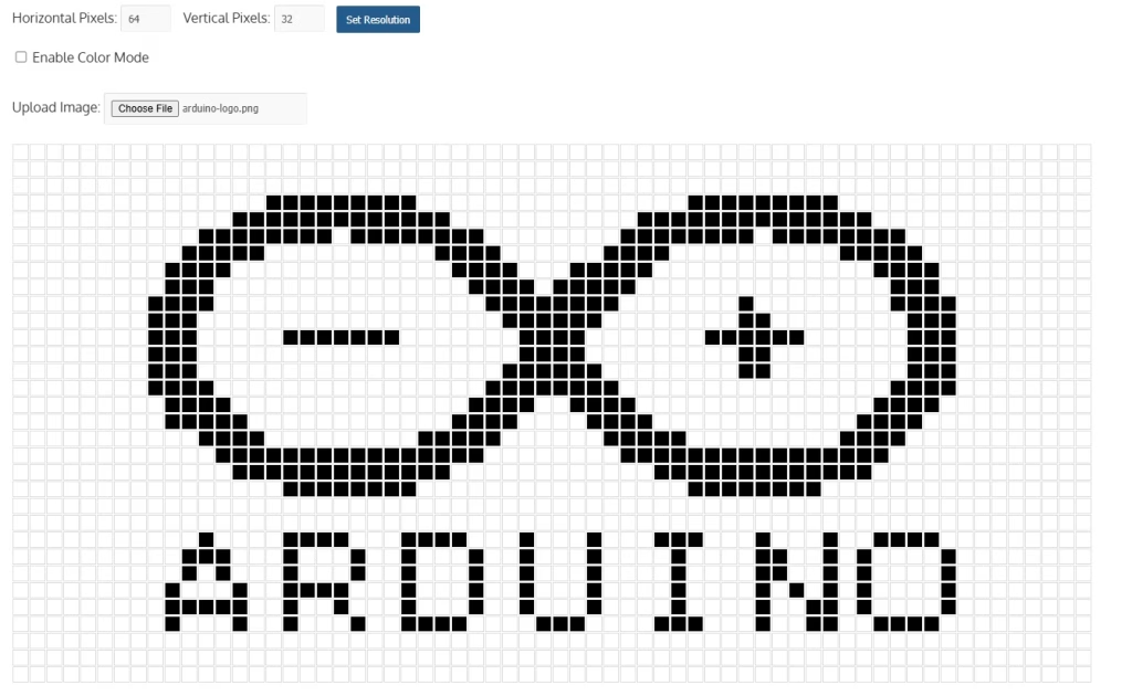
For this purpose, you can use the LCD Bitmap Converter. The tool can convert JPG, PNG, or BMP images into an array that can be included in Arduino and other embedded projects.
Preparing the Image
For the best result:
- Use a simple black-and-white image.
- Remove fine details that will disappear at low resolution.
- Resize the image to the area it will occupy on the display.
- Use strong contrast.
- Avoid converting a full-color photograph directly.
For a full-screen image, set the converter resolution to:
Width: 128
Height: 64
For a smaller logo, use a resolution such as:
Width: 64
Height: 32
After generating the array, place it near the top of your Arduino sketch.
#define logo_width 64
#define logo_height 32

static const unsigned char logo_bits[] = {
 // Replace here with the generated hex data from the LCD bitmap converter
};

The bitmap can then be drawn using:

    u8g2.drawBitmap(
      32,
      4,
      logo_width / 8,
      logo_height,
      logo_bits
    );
The first two parameters are the X and Y coordinates. A 64-pixel-wide bitmap placed at X coordinate 32 will be horizontally centered on a 128-pixel-wide display:

Complete Bitmap Template
#include <Arduino.h>
#include <SPI.h>
#include <U8g2lib.h>

U8G2_ST7920_128X64_1_SW_SPI u8g2(
  U8G2_R0,
  13,
  11,
  10,
  U8X8_PIN_NONE
);

#define logo_width 64
#define logo_height 32

static const unsigned char logo_bits[] = {
  // Replace here with the generated hex data from the LCD bitmap converter
};


void setup() {
  u8g2.begin();
}

void loop() {
  u8g2.firstPage();

  do {
    u8g2.drawBitmap(
      32,
      4,
      logo_width / 8,
      logo_height,
      logo_bits
    );

    u8g2.setFont(u8g2_font_6x10_tr);
    u8g2.drawStr(18, 53, "System Starting");

    u8g2.drawFrame(14, 57, 100, 6);
    u8g2.drawBox(16, 59, 65, 2);

  } while (u8g2.nextPage());

  delay(1000);
}
U8g2’s drawBitmap() function draws a one-bit bitmap stored as row-by-row byte data. Unlike drawXBMP(), its width parameter is specified in bytes rather than pixels, so a 64-pixel-wide image uses a width value of 64 / 8, or 8 bytes. In this example, the 64×32 bitmap occupies 256 bytes of the Arduino Uno’s SRAM.
For larger images or projects that are already using a lot of SRAM, storing the bitmap in program memory and using an XBM-compatible format may be preferable.
Using Hardware SPI
The examples use the software-serial constructor:
U8G2_ST7920_128X64_1_SW_SPI
U8g2 also provides a hardware-SPI constructor:
U8G2_ST7920_128X64_1_HW_SPI u8g2(
  U8G2_R0,
  10,
  U8X8_PIN_NONE
);
With an Arduino Uno, the wiring remains:
| Signal | Arduino Uno |
|---|---|
| SID | D11/MOSI |
| SCLK | D13/SCK |
| CS | D10 |
Hardware SPI may provide faster screen transfers. However, the software constructor is easier to understand and allows other pins to be selected when the normal SPI pins are already being used.
Connecting the LCD Reset Pin to Arduino
Instead of connecting RST permanently to 5V, you can control it using an Arduino pin.
For example, connect the LCD RST pin to D8 and change the constructor to:
U8G2_ST7920_128X64_1_SW_SPI u8g2(
  U8G2_R0,
  13,
  11,
  10,
  8
);
The library can then reset the display during initialization.
Do not leave the RST pin floating. A floating reset input may cause inconsistent startup behavior.
Troubleshooting an Arduino 128×64 LCD
The Backlight Turns On, but Nothing Appears
The backlight and LCD controller are separate parts of the module. A working backlight does not mean that the controller has initialized.
Check the following:
- Adjust the contrast potentiometer.
- Confirm that PSB is connected to GND.
- Check the CS, SID, and SCLK wiring.
- Confirm that the LCD and Arduino share the same ground.
- Check that RST is pulled high.
- Make sure the correct U8g2 constructor is used.
Only Dark Blocks or Random Pixels Appear
This is commonly caused by:
- Incorrect contrast
- A loose ground connection
- PSB left floating
- Incorrect pin order in the constructor
- Unstable reset wiring
- Wires that are too long
- A weak 5V supply
Keep the clock, data, and ground wires reasonably short.
The Display Is Mirrored or Upside Down
Change the rotation parameter.
U8G2_R0  // Normal
U8G2_R1  // 90 degrees
U8G2_R2  // 180 degrees
U8G2_R3  // 270 degrees
For example:
U8G2_ST7920_128X64_1_SW_SPI u8g2(
  U8G2_R2,
  13,
  11,
  10,
  U8X8_PIN_NONE
);
The Bitmap Looks Corrupted
Check that:
- The bitmap width and height match the generated image.
- The correct array name is passed to drawXBMP().
- The array is stored using U8X8_PROGMEM.
- The image uses the expected monochrome/XBM byte order.
- The drawing coordinates do not place part of the image outside the screen.
The Sketch Compiles, but the Arduino Behaves Unpredictably
The program may be running low on SRAM.
Try changing a full-buffer constructor:
U8G2_ST7920_128X64_F_SW_SPI
to the page-buffer version:
U8G2_ST7920_128X64_1_SW_SPI
You can also:
- Use smaller fonts.
- Store constant strings in flash using the F() macro.
- Store bitmap arrays in program memory.
- Remove unused libraries.
- Reduce the number of large global arrays.
The Display Works Until Another SPI Device Is Added
Each SPI device should have its own chip-select signal. Make sure inactive devices have their chip-select pins in the correct inactive state.
Also, verify that the other device does not interfere with the ST7920’s clock or data lines during initialization.
Frequently Asked Questions
Can I power the ST7920 LCD from 3.3 V?
Many common 12864 ST7920 modules are designed for a 5 V supply. Check the module datasheet or PCB markings before using 3.3 V. A 3.3 V microcontroller may also require level shifting depending on the LCD module’s input thresholds.
Can I use an Arduino Mega?
Yes. With the software-serial constructor, you can use almost any digital pins. Simply change both the wiring and constructor values. For hardware SPI on the Mega, use its designated SPI pins.
Can I use an Arduino Nano?
Yes. The classic Arduino Nano uses the same ATmega328P and has the same D10, D11, and D13 signal arrangement used in this tutorial.
Can the ST7920 display color images?
No. The common ST7920 graphical LCD is monochrome. Each pixel is either on or off. The blue, green, or yellow appearance comes from the LCD panel and backlight rather than per-pixel color control.
Can I display live graphs?
Yes. Store a series of sensor readings in an array and draw a line between consecutive points using drawLine(). On an Arduino Uno, keep the history array reasonably small to avoid using too much SRAM.
Can I display numbers using larger fonts?
Yes. U8g2 includes many large numeric and general-purpose fonts. However, larger fonts use more flash memory and occupy more screen space.
Why is my display labeled 12864B instead of ST7920?
“12864B” is often a module or PCB designation. Check the controller marking, seller documentation, or pin labels. The presence of pins such as PSB, SID, SCLK, and VOUT usually indicates an ST7920-style module, but you should still verify the controller before connecting it.
Conclusion
The ST7920 128×64 LCD is a useful upgrade from an ordinary character display. It gives an Arduino enough screen space for menus, sensor dashboards, bar graphs, status icons, and simple user interfaces.
Using serial mode also keeps the wiring manageable. Only three Arduino control pins are needed for CS, serial data, and clock, while the U8g2 library handles the controller’s communication and graphics operations.
Once the basic display is working, try replacing the analog potentiometer example with an actual sensor. You can also create a logo, icon, or splash screen using the LCD Bitmap Converter and display it during project startup.
The same display can be used to build projects such as:
- Digital meters
- Weather stations
- Battery monitors
- Menu-driven controllers
- Data loggers
- Motor-control panels
- Portable test instruments
- Small embedded dashboards
The 128×64 resolution may sound limited compared with modern screens, but with carefully chosen fonts and simple graphics, it is enough to create a clean and practical embedded interface.