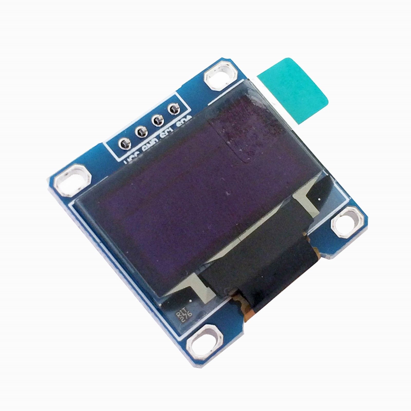
The SSD1306 OLED controller is commonly used in small 128 × 64 and 128 × 32 monochrome displays. Although these modules can show text, lines, shapes, and icons, they cannot normally display a PNG or JPG file directly.
This online SSD1306 bitmap converter turns an uploaded image into a monochrome C++ array compatible with Arduino projects using the Adafruit GFX and Adafruit SSD1306 libraries. It automatically selects the recommended bitmap format, generates an Arduino PROGMEM declaration, and provides a matching drawBitmap() example.
You can resize the image, preview it on an editable pixel grid, correct individual pixels, and check how much flash memory the resulting bitmap will require.
Example: const uint8_t icon[] = { 0x18, 0x3C, 0x7E };
What Is an SSD1306 Bitmap?
An SSD1306 bitmap is a one-bit image in which every pixel is either on or off. Instead of storing full RGB color values, the bitmap packs several pixel states into each byte.
A generated SSD1306-compatible image may look like this:
#define LOGO_WIDTH  16
#define LOGO_HEIGHT 8

const unsigned char logo_data[] PROGMEM = {
    0x0F, 0xF0,
    0x18, 0x18,
    0x30, 0x0C,
    0x67, 0xE6,
    0x67, 0xE6,
    0x30, 0x0C,
    0x18, 0x18,
    0x0F, 0xF0
};
The Adafruit GFX library can read this array and draw the corresponding pixels on an SSD1306 OLED.
Because the display is monochrome, each bit represents one pixel:
- A bit value of 1 represents a foreground pixel
- A bit value of 0 represents a background or transparent pixel
How to Convert an Image for an SSD1306 OLED
1. Select the Bitmap Dimensions
The SSD1306 preset starts with a common 128 × 64 resolution, but you can change the dimensions to match the image you want to create.
The bitmap does not need to occupy the entire OLED screen. For example, a 128 × 64 display can contain:
- A 128 × 64 full-screen startup image
- A 32 × 32 application icon
- A 16 × 16 Wi-Fi symbol
- An 8 × 8 status indicator
Use the actual image dimensions rather than automatically setting every graphic to the full display resolution. Smaller bitmaps consume less flash memory and are faster to draw.
2. Upload or Draw the Image
Upload a PNG, JPG, logo, icon, or other supported image. You can also create the bitmap manually by drawing directly on the pixel grid.
SSD1306 displays are monochrome, so high-contrast source images normally produce the clearest results. Complex photographs, gradients, shadows, and subtle color differences may not convert well to one-bit graphics.
3. Inspect the Monochrome Preview
Review the converted image on the pixel grid. Scaling an image down to a small resolution may remove fine details or create uneven edges.
Click individual pixels to:
- Clean up diagonal lines
- Repair small letters
- Remove isolated pixels
- Improve icon symmetry
- Restore details lost during resizing
4. Check the Output Format
The SSD1306 preset generates a horizontally packed, MSB-first bitmap intended for Adafruit GFX drawBitmap().
The output summary shows:
- Bitmap width and height
- Bytes required per row
- Total array size
- Bit order
- Byte orientation
- Selected output target
5. Generate the Bitmap Array
Click Generate after the image looks correct. Copy the resulting array and the accompanying drawBitmap() call into your Arduino or ESP32 project.
Complete SSD1306 Bitmap Example
The following example shows how to display a generated bitmap using an I2C SSD1306 OLED and the Adafruit libraries:
#include <Wire.h>
#include <Adafruit_GFX.h>
#include <Adafruit_SSD1306.h>

#define SCREEN_WIDTH  128
#define SCREEN_HEIGHT 64
#define OLED_RESET    -1
#define OLED_ADDRESS  0x3C

Adafruit_SSD1306 display(
    SCREEN_WIDTH,
    SCREEN_HEIGHT,
    &Wire,
    OLED_RESET
);

#define LOGO_WIDTH  16
#define LOGO_HEIGHT 16

const unsigned char logo_data[] PROGMEM = {
    0x07, 0xE0,
    0x1F, 0xF8,
    0x38, 0x1C,
    0x60, 0x06,
    0x43, 0xC2,
    0xC7, 0xE3,
    0xCC, 0x33,
    0xD8, 0x1B,
    0xD8, 0x1B,
    0xCC, 0x33,
    0xC7, 0xE3,
    0x43, 0xC2,
    0x60, 0x06,
    0x38, 0x1C,
    0x1F, 0xF8,
    0x07, 0xE0
};

void setup() {
    Wire.begin();

    if (!display.begin(
        SSD1306_SWITCHCAPVCC,
        OLED_ADDRESS
    )) {
        while (true) {
            // OLED initialization failed.
        }
    }

    display.clearDisplay();

    display.drawBitmap(
        56,
        24,
        logo_data,
        LOGO_WIDTH,
        LOGO_HEIGHT,
        SSD1306_WHITE
    );

    display.display();
}

void loop() {
}
The bitmap in this example is positioned at X coordinate 56 and Y coordinate 24. On a 128 × 64 display, this centers a 16 × 16 image.
Understanding drawBitmap()
The Adafruit GFX bitmap-drawing function uses the following basic form:
display.drawBitmap(
    x,
    y,
    bitmap,
    width,
    height,
    color
);
The parameters are:
- x — horizontal position of the image’s upper-left corner
- y — vertical position of the image’s upper-left corner
- bitmap — name of the generated array
- width — image width in pixels
- height — image height in pixels
- color — color used for pixels whose stored bit is 1
For an SSD1306 display, the color is normally:
SSD1306_WHITEYou can erase the same bitmap by drawing it using:
SSD1306_BLACKTransparent and Opaque Bitmap Drawing
The common six-parameter version of drawBitmap() draws only the pixels whose bits are set to 1. Pixels represented by 0 are left unchanged on the existing display buffer.
This makes the bitmap background effectively transparent.
display.drawBitmap(
    10,
    10,
    logo_data,
    LOGO_WIDTH,
    LOGO_HEIGHT,
    SSD1306_WHITE
);
Adafruit GFX also provides a version that accepts both a foreground and background color:
display.drawBitmap(
    10,
    10,
    logo_data,
    LOGO_WIDTH,
    LOGO_HEIGHT,
    SSD1306_WHITE,
    SSD1306_BLACK
);
With this version, bits set to 1 are drawn in the foreground color, while bits set to 0 are drawn in the background color.
This is useful when an icon must completely replace the image previously shown in the same area.
How SSD1306 Bitmap Bytes Are Organized
The converter’s SSD1306 preset produces data for Adafruit GFX drawBitmap(). The image is arranged in horizontal rows, and each group of eight pixels becomes one byte.
Consider the following eight pixels:
1 0 1 1 0 0 1 0With MSB-first packing, the leftmost pixel becomes bit 7 and the rightmost pixel becomes bit 0:
10110010The generated hexadecimal value is:
0xB2If the bit order is reversed, the same group of pixels produces a different byte. Using the wrong order can cause the image to appear mirrored inside each group of eight pixels.
Adafruit GFX Format Versus the SSD1306 Framebuffer
The SSD1306 controller internally organizes display RAM into horizontal pages that are eight pixels tall. Each controller byte normally represents a vertical column of eight pixels within one page.
However, Adafruit GFX drawBitmap() does not require you to provide the image in that native controller memory format. The library reads the horizontally packed bitmap and writes the correct pixels into its own display buffer.
This distinction is important:
- The generated array is formatted for Adafruit GFX drawBitmap()
- It is not necessarily a raw copy of the SSD1306 controller framebuffer
- Code that sends array bytes directly to the SSD1306 controller may require a different layout
Use the generated array with the matching drawing function unless your own driver explicitly expects raw page-oriented SSD1306 data.
Bitmap Widths That Are Not Divisible by Eight
Each bitmap row uses enough complete bytes to contain all of its pixels. The number of bytes per row is:

The total array size is:

For example, a 13 × 7 bitmap requires two bytes for each row:

Only 13 bits in each row represent visible pixels. The remaining three bits in the second byte are padding.
The converter accounts for this padding automatically.
SSD1306 Bitmap Memory Usage
A monochrome bitmap uses one bit per pixel, plus any row-padding bits needed when the width is not divisible by eight.
A full-screen 128 × 64 bitmap requires:

A full-screen 128 × 32 bitmap requires:

A 32 × 32 icon requires:

A 16 × 16 icon requires:

Because the generated declaration uses PROGMEM, the bitmap remains in program flash on AVR-based Arduino boards rather than occupying the same SRAM used by variables and the display buffer.
Displaying Multiple SSD1306 Images
You can store several icons or animation frames as separate arrays:
const unsigned char wifi_icon[] PROGMEM = {
    /* Wi-Fi icon bytes */
};

const unsigned char battery_icon[] PROGMEM = {
    /* Battery icon bytes */
};

const unsigned char warning_icon[] PROGMEM = {
    /* Warning icon bytes */
};
Draw the required image when the corresponding system state changes:
if (wifiConnected) {
    display.drawBitmap(
        0,
        0,
        wifi_icon,
        WIFI_ICON_WIDTH,
        WIFI_ICON_HEIGHT,
        SSD1306_WHITE
    );
}
Remember to call display.display() after drawing. Adafruit SSD1306 normally updates an in-memory buffer first and transfers it to the OLED only when display.display() is called.
Creating a Simple SSD1306 Animation
Multiple bitmap arrays can be displayed in sequence to create a basic animation:
const unsigned char frame_1[] PROGMEM = {
    /* Frame 1 bytes */
};

const unsigned char frame_2[] PROGMEM = {
    /* Frame 2 bytes */
};

void showFrame(
    const unsigned char *frame,
    uint8_t width,
    uint8_t height
) {
    display.clearDisplay();

    display.drawBitmap(
        0,
        0,
        frame,
        width,
        height,
        SSD1306_WHITE
    );

    display.display();
}
Large full-screen animations use considerable flash memory. Small icons or partial-screen animation frames are more practical on memory-constrained boards.
Positioning an SSD1306 Bitmap
To center a bitmap, calculate its starting coordinates from the display and image dimensions:
int16_t x =
    (SCREEN_WIDTH - LOGO_WIDTH) / 2;

int16_t y =
    (SCREEN_HEIGHT - LOGO_HEIGHT) / 2;

display.drawBitmap(
    x,
    y,
    logo_data,
    LOGO_WIDTH,
    LOGO_HEIGHT,
    SSD1306_WHITE
);
This works for any bitmap smaller than the display.
If part of the image extends beyond the display boundary, Adafruit GFX clips the pixels that fall outside the visible area. However, using correct coordinates avoids unnecessary drawing work.
Using the Generated Bitmap with an ESP32
The generated SSD1306 array also works with an ESP32 when the project uses the Arduino framework and Adafruit GFX.
The display initialization is similar, although the I2C pins may differ between ESP32 boards:
#include <Wire.h>
#include <Adafruit_GFX.h>
#include <Adafruit_SSD1306.h>

#define OLED_SDA 21
#define OLED_SCL 22

void setup() {
    Wire.begin(OLED_SDA, OLED_SCL);

    display.begin(
        SSD1306_SWITCHCAPVCC,
        0x3C
    );
}
Change the SDA and SCL pins to match your ESP32 board and wiring.
Common SSD1306 Bitmap Problems
The image is mirrored within every eight pixels
The bitmap was likely generated using the wrong bit order. The Adafruit GFX drawBitmap() format expects MSB-first horizontal bitmap data.
The image looks like vertical stripes
The array may use a vertical or page-oriented byte layout instead of the horizontal format expected by drawBitmap().
The image is completely blank
Check that:
- The OLED initialized successfully
- The correct I2C address is being used
- The bitmap coordinates are inside the display area
- The drawing color is SSD1306_WHITE
- display.display() is called after drawing
The bitmap appears briefly and then disappears
Another part of the program may be calling clearDisplay() or redrawing the display buffer. Draw the bitmap again before the next call to display.display().
The image is inverted
Use the converter’s invert control, reverse the foreground and background colors, or use the display inversion feature when the entire screen should be inverted.
The image dimensions are wrong
Confirm that the width and height passed to drawBitmap() match the dimensions used to generate the array. Incorrect dimensions cause row boundaries to be interpreted incorrectly.
The right edge of the image is corrupted
This often happens when custom drawing code does not account for row padding on widths that are not divisible by eight. Use the generated dimensions and the Adafruit GFX drawing function rather than assuming every row contains exactly width / 8 bytes.
The OLED shows random pixels after startup
Clear the display buffer before drawing the image:
display.clearDisplay();Then call display.display() after adding the bitmap.
Frequently Asked Questions
Can I convert a PNG to an SSD1306 bitmap?
Yes. Upload the PNG, select the required dimensions, review the monochrome preview, edit any incorrect pixels, and generate the SSD1306-compatible array.
Can I convert a JPG for an SSD1306 display?
Yes, but photographs and images containing gradients may lose considerable detail when converted to monochrome. Simple, high-contrast graphics normally produce better results.
Does the image need to be 128 × 64?
No. The bitmap can use any dimensions supported by the drawing function. A 128 × 64 display can show smaller icons and logos at any valid screen position.
Will the output work with a 128 × 32 SSD1306 OLED?
Yes. Set the bitmap dimensions as needed and configure the Adafruit SSD1306 object for a screen height of 32 pixels.
Why is PROGMEM included?
PROGMEM keeps constant bitmap data in program flash on AVR-based Arduino boards. This helps preserve SRAM for variables, the display buffer, and other runtime data.
Can the array be used with SH1106 displays?
The image array may work when the SH1106 library uses the Adafruit GFX drawBitmap() format. Display initialization and buffer handling still depend on the specific SH1106 library.
Can I use this bitmap with U8g2?
Not necessarily. U8g2 drawXBMP() normally expects XBM-compatible LSB-first data. Use the dedicated U8g2 bitmap converter preset for that library.
Can SSD1306 display color images?
Standard SSD1306 OLED modules are monochrome. Each pixel is either on or off, although the physical panel may use white, blue, yellow, or another fixed emitter color.
Can I place several bitmap arrays in one sketch?
Yes. Check the generated byte count for every image and make sure their combined size fits within the board’s available program flash.
Conclusion
An SSD1306 bitmap converter makes it easier to add logos, icons, status symbols, splash screens, and simple animations to Arduino and ESP32 OLED projects. The generated array is formatted for Adafruit GFX drawBitmap() and stored using an Arduino-compatible PROGMEM declaration.
Before copying the data into your project, confirm the bitmap dimensions, memory requirement, drawing coordinates, and selected library. Correct bit order and byte orientation are essential for avoiding mirrored, striped, or scrambled images.