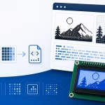
Arduino display libraries usually cannot draw PNG, JPG, or other desktop image files directly. Before an image can appear on an OLED, LCD, LED matrix, or graphical display, its pixels must be converted into numerical data that an Arduino sketch can store and read.
This image to byte array Arduino converter turns an uploaded image into a C++ byte array formatted for Arduino projects. The generated output uses hexadecimal values and an Arduino-compatible PROGMEM declaration, allowing the image data to remain in flash memory instead of consuming limited SRAM.
You can set the bitmap dimensions, upload or draw an image, edit individual pixels, check the estimated memory requirement, and copy the generated byte array into your Arduino sketch.
Example: const uint8_t icon[] = { 0x18, 0x3C, 0x7E };
What Is an Arduino Image Byte Array?
An Arduino image byte array is a sequence of numerical values representing the pixels of an image. Instead of loading a PNG or JPG file, the sketch reads these values and sends the corresponding pixels to a display.
A small monochrome image may produce an array like this:
const unsigned char image_data[] PROGMEM = {
    0x18, 0x3C, 0x7E, 0xDB,
    0xFF, 0x24, 0x5A, 0xA5
};
Each value in the array is one byte. For a monochrome bitmap, one byte can normally store the state of eight pixels.
The exact relationship between the bits and pixels depends on the selected output orientation and bit order. This is why the same image can produce different byte arrays for different Arduino display libraries.
Why Use PROGMEM for Arduino Images?
Many Arduino boards have much less SRAM than flash memory. Large image arrays can quickly use all available SRAM if they are stored as ordinary variables.
For example, the Arduino Uno has only a small amount of working memory compared with its program flash. Storing a full-screen bitmap in SRAM can leave too little memory for variables, display buffers, strings, and library objects.
The PROGMEM keyword tells the Arduino compiler to keep constant data in program flash:
const unsigned char logo[] PROGMEM = {
    0x00, 0x3C, 0x42, 0x81,
    0x81, 0x42, 0x3C, 0x00
};
This is especially useful for:
- OLED logos and splash screens
- Menu icons
- Battery, Wi-Fi, and status symbols
- Graphical LCD images
- LED matrix patterns
- Small animation frames
How to Convert an Image to an Arduino Byte Array
1. Enter the Bitmap Width and Height
Set the width and height required for the image. These values describe the bitmap itself and do not always need to match the complete display resolution.
For example, a 128 × 64 OLED may use:
- A 128 × 64 full-screen splash image
- A 32 × 32 application icon
- A 16 × 16 status symbol
- An 8 × 8 menu indicator
Smaller images use less flash memory and are usually faster to draw.
2. Upload or Draw the Image
Upload an existing PNG, JPG, or other supported image. You can also draw directly on the pixel grid when creating a small icon or symbol.
Simple, high-contrast graphics normally convert better for monochrome displays. Fine details, gradients, and thin lines may disappear when the image is reduced to a small resolution.
3. Review the Pixel Grid
Inspect the converted image before generating the array. Click individual pixels to add missing details, clean up edges, or remove artifacts created during resizing.
Pixel editing is particularly useful for very small graphics because changing a single pixel can noticeably improve readability.
4. Check the Output Settings
The Arduino preset automatically generates an Arduino-compatible declaration using PROGMEM. The output summary also shows the selected dimensions, byte orientation, bit order, and estimated array size.
You can still adjust the available settings when your display library expects a different byte layout.
5. Generate the Byte Array
Click Generate after the image looks correct. Copy the resulting byte array into your Arduino sketch or place it in a separate header file.
Keep the generated width and height values with the array so the drawing function knows the correct bitmap dimensions.
Example Arduino Bitmap Declaration
A generated Arduino bitmap may look like this:
#define LOGO_WIDTH  16
#define LOGO_HEIGHT 8

const unsigned char logo_data[] PROGMEM = {
    0x0F, 0xF0,
    0x18, 0x18,
    0x30, 0x0C,
    0x67, 0xE6,
    0x67, 0xE6,
    0x30, 0x0C,
    0x18, 0x18,
    0x0F, 0xF0
};
Because this bitmap is 16 pixels wide, each row uses two bytes. The eight rows therefore require a total of 16 bytes.
How Monochrome Pixels Become Bytes
A monochrome image normally represents each pixel using one bit:
- 1 for an active pixel
- 0 for an inactive pixel
Eight pixels can be packed into one byte. Consider this row:
1 0 1 1 0 0 1 0When stored MSB first, this becomes:
10110010The hexadecimal equivalent is:
0xB2When the same bits are interpreted in the opposite order, the displayed image may appear mirrored inside each group of eight pixels. Selecting the correct bit order is therefore essential.
Calculating Arduino Bitmap Memory Usage
For a horizontally packed monochrome bitmap, calculate the number of bytes per row using:

The total size is:

A 128 × 64 monochrome bitmap uses:

A 16 × 16 icon uses:

Widths that are not divisible by eight still require a complete final byte for every row. For example, a 13 × 7 image requires:

The unused bits in the final byte act as padding.
Using the Array with Adafruit GFX
Many Arduino OLED and graphical display libraries are based on Adafruit GFX. A compatible monochrome array can be drawn using drawBitmap():
display.drawBitmap(
    0,
    0,
    logo_data,
    LOGO_WIDTH,
    LOGO_HEIGHT,
    1
);
The first two values are the X and Y coordinates. The width and height must match the generated bitmap.
Some libraries use a named color constant instead of the final value:
display.drawBitmap(
    0,
    0,
    logo_data,
    LOGO_WIDTH,
    LOGO_HEIGHT,
    SSD1306_WHITE
);
For a specifically configured SSD1306 bitmap, use the dedicated SSD1306 converter preset because it automatically selects the expected output layout.
Using the Array with U8g2
U8g2 often uses XBM-compatible data with drawXBMP(). XBM data is generally packed differently from the format used by Adafruit GFX.
A U8g2 declaration may look like this:
static const unsigned char logo_data[] U8X8_PROGMEM = {
    /* Generated XBM-compatible bytes */
};
It can then be drawn with:
u8g2.drawXBMP(
    0,
    0,
    LOGO_WIDTH,
    LOGO_HEIGHT,
    logo_data
);
Use the dedicated U8g2 bitmap converter preset when targeting drawXBMP(). Do not assume an Adafruit GFX array will work without changing the bit order or packing format.
Placing the Bitmap in a Header File
For a small sketch, you can place the generated array directly above setup(). For a project containing several images, a separate header file keeps the main sketch easier to read.
Create a file such as images.h:
#ifndef IMAGES_H
#define IMAGES_H

#include <Arduino.h>

#define LOGO_WIDTH  16
#define LOGO_HEIGHT 16

const unsigned char logo_data[] PROGMEM = {
    /* Generated bytes */
};

#endif
Include the header in the main sketch:
#include "images.h"A header guard prevents the file from being processed more than once during compilation.
Reading PROGMEM Data Manually
Most Arduino display libraries that accept bitmap arrays handle flash-memory reads internally. When reading the array yourself on an AVR-based Arduino, use pgm_read_byte():
uint8_t value = pgm_read_byte(&logo_data[index]);An example pixel-reading function for an MSB-first horizontal bitmap is:
uint8_t getBitmapPixel(
    const unsigned char *bitmap,
    uint16_t width,
    uint16_t x,
    uint16_t y
) {
    const uint16_t bytesPerRow = (width + 7u) / 8u;
    const uint32_t byteIndex =
        ((uint32_t)y * bytesPerRow) + (x / 8u);

    const uint8_t bitmapByte =
        pgm_read_byte(&bitmap[byteIndex]);

    const uint8_t bitPosition = 7u - (x % 8u);

    return (bitmapByte >> bitPosition) & 0x01u;
}
This example assumes horizontal packing and MSB-first order. Other output formats require different indexing.
PROGMEM on Different Arduino Boards
The effect of PROGMEM varies between architectures.
AVR Boards
Boards such as the Arduino Uno, Nano, and Mega use separate program and data address spaces. PROGMEM is important because ordinary array access may otherwise copy constant data into SRAM.
ESP32 and ESP8266
These platforms use a different memory architecture, but PROGMEM remains widely supported for compatibility with Arduino libraries. Many constant arrays can be read normally.
RP2040 and ARM-Based Arduino Boards
On many ARM and RP2040 platforms, constant data is already stored in flash as part of the program image. The PROGMEM keyword may have little or no special effect, but keeping it can improve portability between Arduino boards.
Always check the requirements of the target display library and board core.
Common Arduino Bitmap Problems
The image is mirrored or scrambled
The array’s bit order or orientation probably does not match the drawing function. Try the dedicated preset for your display library instead of manually reversing random bytes.
The image appears as vertical or horizontal stripes
The library may expect vertically packed data while the array is arranged in horizontal rows, or the opposite may be true.
The image is inverted
The display driver may interpret 0 and 1 differently. Use the invert control or select the opposite foreground and background color in the drawing function.
The sketch becomes unstable after adding several images
The arrays may be consuming SRAM instead of remaining in flash. Confirm that the declaration includes both const and PROGMEM.
const unsigned char image_data[] PROGMEM = {
    /* Image bytes */
};
The image is cut off
Confirm that the width and height passed to the drawing function match the generated dimensions. Also check that the image does not extend beyond the display boundaries.
The last pixels of each row are wrong
The bitmap width may not be divisible by eight. The drawing code must account for the padded final byte of each row.
The compiler says PROGMEM is undefined
Include the Arduino core header or compile the code as part of an Arduino sketch:
#include <Arduino.h>Frequently Asked Questions
Can I convert PNG and JPG images for Arduino?
Yes. Upload the image, choose the required dimensions, edit the pixel-grid result, and generate the Arduino byte array.
Can Arduino display a PNG file directly?
Not usually. A basic display library normally expects raw bitmap data rather than a compressed PNG. Some more capable boards can decode image files using additional libraries, but this requires more flash, RAM, and processing time.
Should I always use PROGMEM?
It is strongly recommended for image arrays on AVR-based Arduino boards. It is also useful for portability when the same sketch may run on several Arduino-compatible platforms.
Can I store several images in one sketch?
Yes, provided the combined arrays fit in the board’s flash memory. Check the estimated byte count for each image and monitor the compiler’s program-storage report.
Can I animate several byte arrays?
Yes. Store each frame as a separate array and draw them in sequence. Keep the frame size and update rate modest, especially on slower boards or displays.
Why does the same image produce different arrays for U8g2 and Adafruit GFX?
The libraries expect different pixel packing and bit order. The visual image may be identical, but its stored byte representation is not.
Can I use this output with an ESP32?
Yes. ESP32 projects using the Arduino framework can use the generated declaration. Select the specific SSD1306, U8g2, or RGB565 preset when your display library requires one of those formats.
Can this tool generate color image arrays?
Use the RGB565 converter preset for color TFT displays. It generates a 16-bit value for each pixel instead of packing eight monochrome pixels into one byte.
Conclusion
Converting an image to an Arduino byte array makes it possible to store logos, icons, symbols, and other graphics directly in a sketch. The generated PROGMEM declaration helps preserve SRAM, while the editable pixel grid allows you to correct the bitmap before adding it to the project.
Before using the array, verify the bitmap dimensions, bit order, byte orientation, and target display library. Choosing the correct output format prevents mirrored, shifted, or scrambled graphics and makes the generated code easier to integrate.