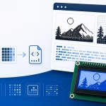
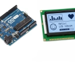
The U8g2 graphics library supports many monochrome LCD and OLED controllers, including SSD1306, SH1106, ST7920, PCD8544, and several e-paper and graphical LCD modules. However, these displays cannot normally draw PNG or JPG image files directly.
This online U8g2 bitmap converter transforms an uploaded image into an XBM-compatible byte array for use with the U8g2 drawXBMP() function. The preset automatically selects horizontal byte packing, LSB-first bit order, and a U8g2-compatible U8X8_PROGMEM declaration.
You can resize the image, inspect the monochrome preview, edit individual pixels, check the required storage size, and copy the generated bitmap into an Arduino, ESP32, STM32, RP2040, or other embedded project using U8g2.
Example: const uint8_t icon[] = { 0x18, 0x3C, 0x7E };
What Is a U8g2 XBM Bitmap?
XBM, short for X BitMap, is a monochrome bitmap format that represents image pixels using C-style array data. U8g2 can draw this format using its drawXBMP() function.
A generated U8g2 image may look like this:
#define LOGO_WIDTH  16
#define LOGO_HEIGHT 8

static const unsigned char logo_data[] U8X8_PROGMEM = {
    0xF0, 0x0F,
    0x18, 0x18,
    0x0C, 0x30,
    0xE6, 0x67,
    0xE6, 0x67,
    0x0C, 0x30,
    0x18, 0x18,
    0xF0, 0x0F
};
Each hexadecimal value represents one byte. For a monochrome image, every bit in that byte represents one pixel.
U8g2 drawXBMP() expects XBM-compatible data. Pixels are packed horizontally, and the first pixel in each byte is stored in the least significant bit.
How to Convert an Image for U8g2
1. Set the Bitmap Dimensions
Enter the width and height of the image you want to create. These values describe the bitmap itself and do not have to match the full physical display resolution.
For example, a 128 × 64 OLED can display:
- A 128 × 64 full-screen startup image
- A 64 × 32 logo
- A 32 × 32 application icon
- A 16 × 16 status symbol
- An 8 × 8 menu marker
Smaller images require less flash memory and take less time to draw.
2. Upload or Draw an Image
Upload a PNG, JPG, logo, icon, or other supported image. You can also create the image manually by clicking cells on the pixel grid.
U8g2 is primarily designed for monochrome displays, so simple high-contrast images generally produce the best results. Photographs, gradients, anti-aliased text, and subtle color differences may lose detail when converted to one-bit output.
3. Edit the Converted Pixels
Inspect the converted image on the pixel grid. When a large source image is reduced to a small bitmap, thin lines and fine details may disappear or become uneven.
Use the grid editor to:
- Remove isolated pixels
- Repair broken lines
- Improve small text
- Clean up curves and diagonals
- Make icons more symmetrical
4. Verify the U8g2 Output Format
The U8g2 preset automatically selects an XBM-compatible layout:
- Monochrome output
- Horizontal byte packing
- LSB-first bit order
- U8X8_PROGMEM storage declaration
- A matching drawXBMP() example
The output summary also shows the image dimensions, bytes per row, total array size, byte orientation, and bit order.
5. Generate the XBM Array
Click Generate after the preview looks correct. Copy the generated array and the accompanying U8g2 drawing code into your project.
Complete U8g2 Bitmap Example
The following example displays a generated bitmap on a 128 × 64 SSD1306 OLED using the U8g2 full-buffer mode:
#include <Arduino.h>
#include <U8g2lib.h>
#include <Wire.h>

U8G2_SSD1306_128X64_NONAME_F_HW_I2C u8g2(
    U8G2_R0,
    U8X8_PIN_NONE
);

#define LOGO_WIDTH  16
#define LOGO_HEIGHT 16

static const unsigned char logo_data[] U8X8_PROGMEM = {
    0xE0, 0x07,
    0xF8, 0x1F,
    0x1C, 0x38,
    0x06, 0x60,
    0xC2, 0x43,
    0xE3, 0xC7,
    0x33, 0xCC,
    0x1B, 0xD8,
    0x1B, 0xD8,
    0x33, 0xCC,
    0xE3, 0xC7,
    0xC2, 0x43,
    0x06, 0x60,
    0x1C, 0x38,
    0xF8, 0x1F,
    0xE0, 0x07
};

void setup() {
    u8g2.begin();

    u8g2.clearBuffer();

    u8g2.drawXBMP(
        56,
        24,
        LOGO_WIDTH,
        LOGO_HEIGHT,
        logo_data
    );

    u8g2.sendBuffer();
}

void loop() {
}
The bitmap is placed at X coordinate 56 and Y coordinate 24. This centers a 16 × 16 image on a 128 × 64 screen.
Understanding drawXBMP()
The U8g2 XBM drawing function uses the following form:
u8g2.drawXBMP(
    x,
    y,
    width,
    height,
    bitmap
);
The parameters are:
- x — horizontal coordinate of the bitmap’s upper-left corner
- y — vertical coordinate of the bitmap’s upper-left corner
- width — bitmap width in pixels
- height — bitmap height in pixels
- bitmap — name of the generated XBM array
Unlike some graphics-library functions, drawXBMP() places the width and height before the array name.
The current drawing color controls whether active bitmap pixels are set, cleared, or toggled.
Setting the U8g2 Drawing Color
U8g2 uses setDrawColor() to control how drawing operations affect the display buffer.
To turn on pixels represented by 1:
u8g2.setDrawColor(1);To clear those pixels:
u8g2.setDrawColor(0);To toggle the existing pixels:
u8g2.setDrawColor(2);A typical sequence is:
u8g2.clearBuffer();
u8g2.setDrawColor(1);

u8g2.drawXBMP(
    0,
    0,
    LOGO_WIDTH,
    LOGO_HEIGHT,
    logo_data
);

u8g2.sendBuffer();
Why U8g2 Uses LSB-First Bitmap Data
In XBM-compatible data, the first pixel in each group of eight is stored in bit 0, which is the least significant bit.
Consider this row of pixels:
1 0 1 1 0 0 1 0The first pixel is stored in bit 0, the second pixel in bit 1, and so on. The resulting bit positions are:
Bit position: 7 6 5 4 3 2 1 0
Pixel value:  0 1 0 0 1 1 0 1
The resulting binary value is:
01001101Its hexadecimal value is:
0x4DThe same visual row stored in MSB-first order would produce a different byte. This is why an Adafruit GFX bitmap should not automatically be used with U8g2 drawXBMP().
U8g2 drawXBMP() Versus drawBitmap()
U8g2 includes bitmap-related functions that may use different data conventions. The most important distinction for generated image arrays is between XBM-compatible data and other bitmap layouts.
The U8g2 preset on this page is specifically configured for:
u8g2.drawXBMP()It generates:
- Horizontal rows
- LSB-first bits
- XBM-compatible bytes
- A U8X8_PROGMEM declaration
If you call another bitmap function, confirm that it expects the same packing and bit order.
Using U8X8_PROGMEM
The generated bitmap declaration uses:
static const unsigned char logo_data[] U8X8_PROGMEM = {
    /* Generated XBM bytes */
};
U8X8_PROGMEM allows the U8g2 library to apply the appropriate program-memory attribute for the selected platform.
On AVR-based boards, this helps keep constant bitmap data in flash rather than consuming limited SRAM. On other architectures, the macro maintains compatibility with the library’s data-reading functions.
Using the U8g2 macro is generally preferable to manually replacing it with an architecture-specific storage attribute.
Using a Full-Buffer U8g2 Constructor
U8g2 constructors containing _F_ normally use a full display buffer. A full-buffer drawing sequence looks like this:
u8g2.clearBuffer();

u8g2.drawXBMP(
    0,
    0,
    LOGO_WIDTH,
    LOGO_HEIGHT,
    logo_data
);

u8g2.sendBuffer();
clearBuffer() clears the memory buffer, while sendBuffer() transfers the completed frame to the display.
For a 128 × 64 monochrome display, a complete framebuffer requires approximately 1,024 bytes of RAM.
Using a Page-Buffer U8g2 Constructor
Memory-constrained boards may use a page-buffer constructor containing _1_ or _2_ instead of _F_. In this mode, the drawing commands must be repeated for every page:
u8g2.firstPage();

do {
    u8g2.drawXBMP(
        0,
        0,
        LOGO_WIDTH,
        LOGO_HEIGHT,
        logo_data
    );
} while (u8g2.nextPage());
Do not call clearBuffer() and sendBuffer() when using the page-buffer loop unless the selected constructor and library mode explicitly support that workflow.
All drawing operations that should appear in the frame must remain inside the do...while block.
Bitmap Widths That Are Not Multiples of Eight
An XBM row does not need to be exactly 8, 16, 24, or 32 pixels wide. However, every row must contain enough complete bytes to store all of its pixels.
The number of bytes per row is:

The total array size is:

For example, a 13 × 7 image requires:

Each row uses two bytes. Only five bits of the second byte represent visible pixels, while the remaining bits are padding.
U8g2 Bitmap Memory Usage
A monochrome XBM image uses one bit per pixel, plus any padding required at the end of each row.
A full-screen 128 × 64 bitmap requires:

A 64 × 32 logo requires:

A 32 × 32 icon requires:

A 16 × 16 icon requires:

The generated data is normally stored in flash, but the U8g2 display buffer itself may use additional RAM depending on the selected constructor.
Centering a U8g2 Bitmap
Calculate the upper-left coordinates from the display and bitmap dimensions:
const int16_t x =
    (u8g2.getDisplayWidth() - LOGO_WIDTH) / 2;

const int16_t y =
    (u8g2.getDisplayHeight() - LOGO_HEIGHT) / 2;

u8g2.drawXBMP(
    x,
    y,
    LOGO_WIDTH,
    LOGO_HEIGHT,
    logo_data
);
This allows the same positioning code to work with different display dimensions and rotations.
Displaying Multiple U8g2 Images
You can store several icons as separate XBM arrays:
static const unsigned char wifi_icon[] U8X8_PROGMEM = {
    /* Wi-Fi icon bytes */
};

static const unsigned char battery_icon[] U8X8_PROGMEM = {
    /* Battery icon bytes */
};

static const unsigned char warning_icon[] U8X8_PROGMEM = {
    /* Warning icon bytes */
};
Draw the appropriate icon based on the current system state:
if (wifiConnected) {
    u8g2.drawXBMP(
        0,
        0,
        WIFI_ICON_WIDTH,
        WIFI_ICON_HEIGHT,
        wifi_icon
    );
}
For a full-buffer constructor, call sendBuffer() after all text, icons, and graphics have been drawn.
Creating a U8g2 Bitmap Animation
Store each animation frame as a separate array:
static const unsigned char frame_1[] U8X8_PROGMEM = {
    /* First frame */
};

static const unsigned char frame_2[] U8X8_PROGMEM = {
    /* Second frame */
};
A simple full-buffer frame function can be written as:
void showFrame(
    const unsigned char *frame,
    uint8_t width,
    uint8_t height
) {
    u8g2.clearBuffer();

    u8g2.drawXBMP(
        0,
        0,
        width,
        height,
        frame
    );

    u8g2.sendBuffer();
}
Large full-screen animations require considerable flash memory. Small icons and partial-screen frames are usually more practical.
Using the Bitmap with an ST7920 Display
U8g2 supports common 128 × 64 ST7920 graphical LCD modules. After selecting the correct constructor, the same generated XBM data can be drawn using drawXBMP().
A software-SPI constructor may resemble:
U8G2_ST7920_128X64_F_SW_SPI u8g2(
    U8G2_R0,
    clockPin,
    dataPin,
    chipSelectPin,
    U8X8_PIN_NONE
);
The drawing code remains:
u8g2.drawXBMP(
    x,
    y,
    LOGO_WIDTH,
    LOGO_HEIGHT,
    logo_data
);
The correct constructor depends on the display controller, interface, selected pins, and buffer mode.
Using the Bitmap with an ESP32
The generated array can also be used with U8g2 on an ESP32. For an I2C OLED, initialize the interface using the required SDA and SCL pins before starting U8g2.
#include <Wire.h>
#include <U8g2lib.h>

#define OLED_SDA 21
#define OLED_SCL 22

U8G2_SSD1306_128X64_NONAME_F_HW_I2C u8g2(
    U8G2_R0,
    U8X8_PIN_NONE
);

void setup() {
    Wire.begin(OLED_SDA, OLED_SCL);
    u8g2.begin();
}
Change the pin numbers to match the selected ESP32 board.
Common U8g2 Bitmap Problems
The image is mirrored inside each byte
The bitmap was probably generated using MSB-first order. U8g2 drawXBMP() expects XBM-compatible LSB-first data.
The bitmap works with Adafruit GFX but not U8g2
Adafruit GFX drawBitmap() and U8g2 drawXBMP() use different bit orders. Generate the bitmap specifically with the U8g2 preset instead of reusing the same array.
The display remains blank
Check that:
- The correct U8g2 constructor is selected
- u8g2.begin() has been called
- The bitmap coordinates are inside the screen area
- The drawing color is set to 1
- sendBuffer() is called in full-buffer mode
- The page loop is used correctly in page-buffer mode
Only part of the image appears
The width or height passed to drawXBMP() may not match the dimensions used when generating the array. The image may also extend beyond the display boundary.
The image appears as stripes or random blocks
The source array may use vertical or controller-page packing rather than horizontal XBM rows.
The image is inverted
Invert the source bitmap in the converter or change the drawing behavior with setDrawColor().
The right edge is corrupted
The bitmap width may not be divisible by eight. Custom byte-reading code must use the rounded-up number of bytes per row.
The image disappears after another drawing operation
A later call to clearBuffer(), firstPage(), or another full-frame redraw may replace the previous bitmap. Draw all required elements during the same frame update.
The compiler reports that U8X8_PROGMEM is undefined
Make sure the U8g2 header is included before the bitmap declaration:
#include <U8g2lib.h>Frequently Asked Questions
Can I convert a PNG to a U8g2 bitmap?
Yes. Upload the PNG, select the required dimensions, edit the monochrome preview, and generate the XBM-compatible array.
Can I convert a JPG for U8g2?
Yes, although photographs and gradients lose detail when reduced to monochrome. High-contrast icons and logos normally produce better results.
What is the difference between XBM and XBMP?
XBM refers to the monochrome bitmap data format. U8g2 names its corresponding drawing function drawXBMP().
Why is the generated array LSB first?
XBM stores the first pixel of each eight-pixel group in the least significant bit. This is the byte order expected by U8g2 drawXBMP().
Should I use PROGMEM or U8X8_PROGMEM?
For U8g2 bitmap data, U8X8_PROGMEM is preferable because it lets the library apply the appropriate program-memory handling for the selected platform.
Can I use the output with an SSD1306 OLED?
Yes, when the display is controlled through U8g2 and the image is drawn using drawXBMP(). Use the separate SSD1306 preset when working with Adafruit GFX drawBitmap().
Can I use the output with an ST7920 LCD?
Yes. Select the correct U8g2 ST7920 constructor and draw the generated array with drawXBMP().
Does the bitmap need to match the full display resolution?
No. You can generate small icons, logos, buttons, status indicators, or partial-screen graphics.
Can I store multiple U8g2 images?
Yes. Each image can use its own XBM array. Check the generated size of every image to ensure their combined storage requirement fits in program flash.
Can this preset create color images?
No. U8g2 is primarily intended for monochrome displays. For color TFT graphics, use the RGB565 image converter preset.
Conclusion
A U8g2 bitmap converter allows you to add logos, icons, splash screens, symbols, and simple animations to supported monochrome displays without manually calculating XBM bytes.
The generated output uses horizontal XBM packing, LSB-first bit order, and a U8X8_PROGMEM declaration for use with U8g2 drawXBMP(). Before adding the array to your project, verify the dimensions, display constructor, buffer mode, drawing coordinates, and memory requirement.