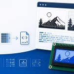
Bitmap arrays are useful for storing icons, logos, and display graphics directly in embedded firmware. However, once an image has been converted into hexadecimal values, it can be difficult to tell what the array contains without loading it onto physical hardware.
This online bitmap array to image converter reconstructs a visual image from C, C++, Arduino, XBM, and RGB565 array data. Paste an existing declaration, enter the image dimensions, select the correct byte layout, and the tool will rebuild the bitmap on an editable pixel grid.
You can use the reconstructed preview to identify unknown assets, debug incorrect bit order, repair individual pixels, convert between display-library formats, and export the result as a PNG image.
Example: const uint8_t icon[] = { 0x18, 0x3C, 0x7E };
What Is a Bitmap Array to Image Converter?
A bitmap array stores image data as a sequence of numerical values. These values may represent groups of monochrome pixels, individual RGB565 colors, or raw bytes intended for a particular graphics library.
For example, this eight-byte array can represent an 8 × 8 monochrome image:
const uint8_t icon[] = {
    0x18,
    0x3C,
    0x7E,
    0xDB,
    0xFF,
    0x24,
    0x5A,
    0xA5
};
Looking at the values alone does not clearly reveal the image. The converter reads each bit, places it at the correct X and Y coordinate, and displays the reconstructed pixels visually.
The same basic process can be used for:
- Generic C bitmap arrays
- Arduino PROGMEM arrays
- Adafruit GFX drawBitmap() data
- SSD1306 bitmap arrays
- U8g2 and XBM drawXBMP() data
- RGB565 uint16_t color arrays
- RGB565 raw byte streams
How to Convert a Bitmap Array Back to an Image
1. Paste the Bitmap Array
Paste the array into the input area. You can paste either the complete C or C++ declaration or only the numerical values.
A complete declaration may look like this:
#define ICON_WIDTH  16
#define ICON_HEIGHT 16

const unsigned char icon_data[] PROGMEM = {
    0x00, 0x18, 0x3C, 0x7E,
    0xFF, 0xDB, 0x81, 0x00
};
The tool ignores common declarations, braces, commas, comments, storage attributes, and variable names. Only the numerical values inside the array initializer are treated as image data.
You can also paste plain values:
0x18, 0x3C, 0x7E, 0xDB,
0xFF, 0x24, 0x5A, 0xA5
2. Enter the Image Width and Height
Array data usually does not contain enough information to determine the image dimensions automatically. Enter the width and height used when the original image was generated.
For example, eight bytes could represent:
- An 8 × 8 horizontal monochrome image
- A 16 × 4 horizontal monochrome image
- A differently arranged vertical bitmap
- Four RGB565 pixels stored as raw bytes
The dimensions must match the selected format for the image to reconstruct correctly.
3. Select the Array Format
Choose the format that matches the source array. Available options may include:
- Generic monochrome, MSB first
- Generic monochrome, LSB first
- Adafruit GFX or SSD1306 drawBitmap()
- U8g2 or XBM drawXBMP()
- RGB565 16-bit values
- RGB565 high-byte-first data
- RGB565 low-byte-first data
Selecting a library preset automatically configures the expected bit order and packing method. You can still adjust the individual settings when working with a custom display driver.
4. Reconstruct the Image
Click Reconstruct Image. The converter checks whether the number of values matches the selected width, height, and data format.
If the data length is correct, the tool decodes the array and fills the editable image grid.
If the data is too short or too long, the tool displays the expected and parsed sizes instead of silently discarding or inventing values.
5. Inspect and Edit the Pixels
Review the reconstructed image on the grid. If the image is recognizable but mirrored, inverted, striped, or incorrectly colored, adjust the format settings and reconstruct it again.
After obtaining the correct layout, you can edit individual pixels to repair the image or remove unwanted details.
6. Export the Image or Generate a New Array
Download the reconstructed grid as a PNG image, or switch back to the image-to-array mode and generate the edited asset in another format.
For example, you can reconstruct a U8g2 XBM array and then convert the same image into an Adafruit GFX SSD1306 array.
Supported Number Formats
The converter can read several common numerical formats used in embedded source code.
Hexadecimal Values
0x18, 0x3C, 0x7E, 0xDBHexadecimal is the most common format for bitmap arrays because one byte can be written compactly using two hexadecimal digits.
Binary Values
0b00011000,
0b00111100,
0b01111110
Binary notation makes individual bits easier to inspect but produces longer source files.
Decimal Values
24, 60, 126, 219Decimal arrays are less common for bitmaps but can still be decoded because they represent the same numerical values.
Mixed Number Formats
The parser can also read a mixture of supported values:
0b00011000, 60, 0x7E, 219These values are interpreted as:
24, 60, 126, 219Using Full C and Arduino Declarations
You do not need to remove C syntax before pasting an array. The tool can extract values from common declarations such as:
static const unsigned char logo[] U8X8_PROGMEM = {
    0xF0, 0x0F,
    0x18, 0x18,
    0x0C, 0x30,
    0xE6, 0x67
};
It can also ignore comments:
const uint8_t logo[] PROGMEM = {
    0x18, // First row
    0x3C, // Second row
    0x7E, /* Third row */
    0xDB
};
Numbers appearing in declarations, dimensions, comments, or array sizes are not treated as bitmap values when they are outside the selected array initializer.
If the pasted code contains several separate arrays, paste one array at a time so the tool does not combine unrelated images.
Understanding MSB-First Bitmap Arrays
In an MSB-first horizontal bitmap, the leftmost pixel in each eight-pixel group is stored in bit 7. The rightmost pixel is stored in bit 0.
Consider this row:
1 0 1 1 0 0 1 0Its MSB-first binary representation is:
10110010The hexadecimal value is:
0xB2This arrangement is commonly used with Adafruit GFX drawBitmap() and the corresponding SSD1306 bitmap preset.
For a pixel at coordinate X, the bit position is:

Understanding LSB-First and XBM Arrays
XBM-compatible arrays store the first pixel in bit 0 rather than bit 7. This format is commonly used by U8g2 drawXBMP().
For the same visual row:
1 0 1 1 0 0 1 0The bit positions become:
Bit:    7 6 5 4 3 2 1 0
Value:  0 1 0 0 1 1 0 1
The resulting value is:
0x4DFor LSB-first data, the pixel bit position is:

If an XBM array is decoded as MSB first, the result often appears mirrored within every group of eight pixels.
Calculating the Required Monochrome Byte Count
For horizontally packed monochrome data, each row must contain enough complete bytes to store all of its pixels.
The number of bytes required per row is:

The total expected byte count is:

For a 16 × 16 image:

For a 13 × 7 image:

The last byte in each 13-pixel row contains three unused padding bits. These bits are ignored when reconstructing the visible image.
Why Array Length Validation Matters
An incorrect width or height causes the parser to place row boundaries in the wrong locations. The image may appear shifted, wrapped, or completely scrambled even when the array itself is valid.
Suppose a 16 × 16 monochrome bitmap requires 32 bytes, but the pasted array contains only 24 bytes. The converter cannot reconstruct the missing rows reliably.
Instead of silently adding zeros, it reports:
Expected: 32 bytes
Parsed: 24 bytes
Status: Not enough data
Likewise, if an array contains too many values, the tool does not automatically discard them. The extra data may indicate:
- An incorrect image height
- Multiple animation frames
- A second bitmap array
- A different packing method
- Incorrectly parsed metadata
Reconstructing Adafruit GFX and SSD1306 Arrays
For an array used with:
display.drawBitmap(
    x,
    y,
    bitmap,
    width,
    height,
    SSD1306_WHITE
);
Select the Adafruit GFX or SSD1306 format. This normally configures:
- Monochrome data
- Horizontal rows
- MSB-first bit order
- One bit per pixel
Do not select native SSD1306 page-oriented data unless the source array was sent directly to the controller rather than passed through Adafruit GFX.
The internal SSD1306 framebuffer layout is not necessarily the same as the bitmap format accepted by drawBitmap().
Reconstructing U8g2 and XBM Arrays
For an array drawn using:
u8g2.drawXBMP(
    x,
    y,
    width,
    height,
    bitmap
);
Select the U8g2/XBM format. This configures:
- Monochrome data
- Horizontal rows
- LSB-first bit order
- XBM-compatible packing
Arrays declared with U8X8_PROGMEM can be pasted without removing the storage macro.
Reconstructing RGB565 Arrays
An RGB565 array stores one 16-bit color value for every pixel.
For example:
const uint16_t colors[] = {
    0xF800, 0x07E0, 0x001F, 0xFFFF,
    0x0000, 0xFFE0, 0xF81F, 0x07FF
};
These values represent:
- Red
- Green
- Blue
- White
- Black
- Yellow
- Magenta
- Cyan
For an RGB565 uint16_t array, the expected value count is:

A 32 × 32 image therefore requires:

Since every value contains two bytes, the total data size is:

How RGB565 Colors Are Reconstructed
RGB565 divides a 16-bit value into:
- 5 red bits
- 6 green bits
- 5 blue bits
The packed arrangement is:
RRRRRGGG GGGBBBBBThe original components are extracted using:
red5   = (value >> 11) & 0x1F;
green6 = (value >> 5)  & 0x3F;
blue5  = value & 0x1F;
These reduced components are expanded back into approximate 8-bit values for the browser preview.
Because RGB565 contains fewer color levels than RGB888, the reconstructed PNG may not exactly match the source image that existed before conversion. This is expected color quantization rather than a decoding error.
Reconstructing Raw RGB565 Bytes
Some embedded projects store RGB565 pixels as explicit byte streams instead of uint16_t values.
High-byte-first data may look like:
0xF8, 0x00,
0x07, 0xE0,
0x00, 0x1F
These byte pairs represent:
- 0xF800 — red
- 0x07E0 — green
- 0x001F — blue
For high-byte-first input:

Low-byte-first data places the bytes in the opposite order:
0x00, 0xF8,
0xE0, 0x07,
0x1F, 0x00
Selecting the wrong byte order usually preserves the overall image shape but produces incorrect colors.
RGB565 Versus BGR565
Some display controllers or libraries use BGR channel order rather than RGB. In BGR565, the red and blue fields are exchanged. A common sign of incorrect channel order is that red areas appear blue while green remains mostly correct. When this happens, switch between RGB565 and BGR565 interpretation and reconstruct the image again.
Editing the Reconstructed Image
After decoding the array, the image appears on the same editable grid used by the forward converter.
You can:
- Turn monochrome pixels on or off
- Change individual RGB565 pixel colors
- Repair damaged icons
- Remove unwanted artifacts
- Correct asymmetrical shapes
- Modify an existing firmware asset without locating the original source image
The edited grid becomes the new source image. You can then regenerate the array in the original format or convert it to another library format.
Converting Between Bitmap Array Formats
The reverse converter can be used as a bridge between incompatible graphics libraries.
For example:
- Paste a U8g2 XBM array.
- Select U8g2/XBM and reconstruct the image.
- Edit the bitmap if needed.
- Switch to Image to Array mode.
- Select SSD1306/Adafruit GFX.
- Generate the new MSB-first array.
The visual image remains the same, but the byte values change because U8g2 XBM and Adafruit GFX use different bit orders.
You can use the same workflow to:
- Convert Adafruit GFX data to U8g2
- Convert generic C arrays to Arduino PROGMEM
- Inspect and edit RGB565 graphics
- Create PNG backups of firmware assets
Downloading the Reconstructed Image as PNG
After reconstructing and editing the image, click Download PNG to export the current grid. The exported file is created locally in the browser. The array data and resulting image are not uploaded to the server. For small pixel-art images, use a scaled export option when available. Scaling an 8 × 8 icon to 8× produces a 64 × 64 PNG while preserving the block-like pixel appearance. Image smoothing should remain disabled so pixels retain sharp edges rather than becoming blurred.
Monochrome PNG Colors
A monochrome array stores only on and off states. It does not necessarily contain actual black and white color information.
When exporting a PNG, choose:
- A foreground color for active pixels
- A background color for inactive pixels
- An optional transparent background
These choices affect only the PNG appearance. They do not change the underlying one-bit image data.
Common Bitmap Array Reconstruction Problems
The image is mirrored in eight-pixel sections
The selected bit order is incorrect. Switch between MSB first and LSB first.
The image appears as diagonal or shifted rows
The width is probably incorrect, causing each new row to begin at the wrong byte position.
The image appears as vertical stripes
The array may use a vertical or page-oriented layout rather than horizontal rows.
The image is upside down
The rows may be stored in bottom-to-top order by a custom converter or image format. Reverse the row order before decoding or use an available vertical-flip option.
The image is inverted
The source library may interpret 0 as an active pixel and 1 as inactive. Enable Invert pixels and reconstruct the image again.
The tool reports too few bytes
Check the width, height, data format, and whether the pasted code contains the complete array.
The tool reports too many bytes
The input may contain multiple frames, extra metadata, a second array, or incorrect dimensions.
RGB565 colors are incorrect
Try the opposite byte order or switch between RGB565 and BGR565.
The RGB565 image is recognizable but has unusual colors
The source may be byte-swapped. Select high-byte-first or low-byte-first raw input as appropriate.
The parser finds values that are not part of the image
Paste only one array declaration. Avoid combining several arrays, lookup tables, or animation frames in the same input.
The exported PNG looks pixelated
That is normal for low-resolution embedded graphics. Use a scaled export with image smoothing disabled when you need a larger preview with sharp pixel edges.
Frequently Asked Questions
Can I convert a C array back into an image?
Yes. Paste the array, enter its width and height, choose the correct packing format, and reconstruct the image.
Can I paste a complete Arduino PROGMEM declaration?
Yes. The converter can ignore common C++ syntax and extract the numerical values from the initializer.
Can I view a U8g2 bitmap array?
Yes. Select the U8g2/XBM preset so the array is decoded using horizontal LSB-first packing.
Can I view an Adafruit GFX SSD1306 array?
Yes. Select the Adafruit GFX or SSD1306 format, which normally uses horizontal MSB-first data for drawBitmap().
Can I convert an RGB565 array into a PNG?
Yes. Select RGB565 16-bit values or the appropriate raw-byte order, reconstruct the image, and download the result as PNG.
Why do I need to enter the width and height?
The same number of bytes can represent several possible image dimensions. Most raw arrays contain no reliable metadata describing their shape.
Can the converter determine the dimensions automatically?
It may suggest possible dimensions when the byte count and width are compatible, but it cannot always determine the original dimensions uniquely.
Can I edit the reconstructed bitmap?
Yes. After decoding, the pixels remain editable on the grid.
Can I convert the reconstructed image into another array format?
Yes. Switch to Image to Array mode, select another output target, and generate a new array from the current grid.
Can I paste binary or decimal arrays?
Yes. The parser supports common hexadecimal, binary, and decimal integer formats.
Does the tool execute pasted C or C++ code?
No. It treats the input only as text and extracts supported numerical values without compiling or executing the code.
Are pasted arrays uploaded to the server?
No. Parsing, reconstruction, editing, and PNG generation occur locally in the browser.
Can I reconstruct animation frames?
Paste and reconstruct one frame at a time. Arrays containing multiple frames should be separated before use unless the tool explicitly adds multi-frame support later.
Conclusion
A bitmap array to image converter makes it possible to inspect graphics that exist only as C, C++, Arduino, XBM, or RGB565 source data. It is useful for debugging display code, identifying unknown assets, repairing bitmap arrays, and recovering images when the original PNG or design file is unavailable.
For an accurate reconstruction, confirm the image dimensions, bit order, byte layout, color format, and byte order. Once the image appears correctly, you can edit its pixels, download it as PNG, or convert it into a different embedded-display array format.