The Raspberry Pi 5 is powerful enough to run vision, robotics, and automation projects, but its GPIO pins cannot directly drive DC motors. A motor needs more current than a Raspberry Pi GPIO pin can provide, and motors also generate electrical noise that can damage sensitive electronics.
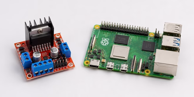
That is where the L298N motor driver module comes in. In this tutorial, you will learn how to connect an L298N to a Raspberry Pi 5 and control one or two DC motors using Python.
We will cover the wiring, power supply setup, GPIO pin connections, Python code, motor direction control, PWM speed control, and common troubleshooting tips.
Why Use an L298N with Raspberry Pi 5?
The Raspberry Pi 5 GPIO pins are for logic signals, not motor power. A GPIO pin can switch between LOW and HIGH, but it cannot safely supply the current needed by a DC motor.
The L298N module acts as a bridge between the Raspberry Pi 5 and the motor. The Raspberry Pi sends control signals to the L298N, and the L298N handles the higher motor voltage and current.
With an L298N module, you can:
- Control the direction of a DC motor
- Control the speed of a DC motor using PWM
- Drive two DC motors independently
- Build a simple Raspberry Pi robot car
- Control small pumps, fans, gear motors, or other DC loads
Parts Needed
For this project, you will need:
- Raspberry Pi 5
- L298N motor driver module
- One or two DC motors
- External motor power supply, such as a 6V, 7.4V, 9V, or 12V battery pack
- Jumper wires
- Breadboard or screw terminals
- Raspberry Pi OS installed on your Raspberry Pi 5
Do not power the motors directly from the Raspberry Pi 5 GPIO pins. Use a separate motor power supply connected to the L298N module.
L298N Motor Driver Pinout
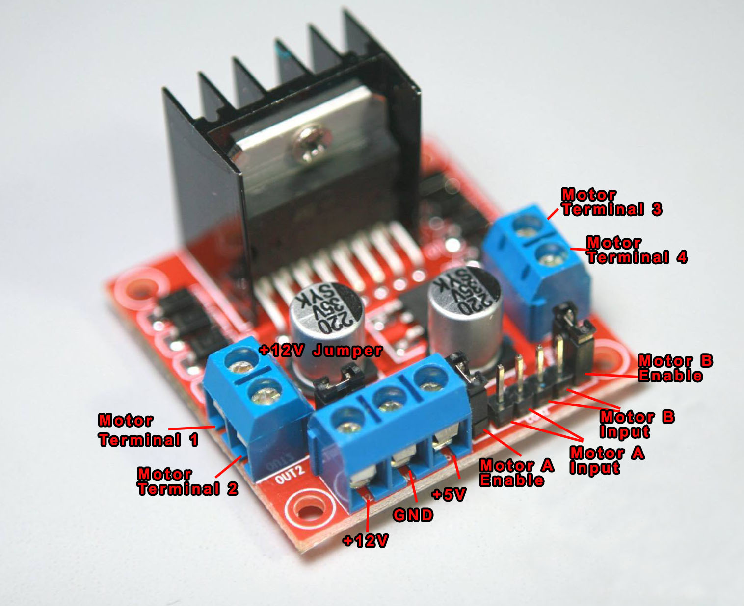
Most L298N modules have the following pins:
| L298N Pin | Description |
|---|---|
| OUT1, OUT2 | Motor A output terminals |
| OUT3, OUT4 | Motor B output terminals |
| IN1, IN2 | Direction control pins for Motor A |
| IN3, IN4 | Direction control pins for Motor B |
| ENA | Speed control / enable pin for Motor A |
| ENB | Speed control / enable pin for Motor B |
| +12V / VIN | External motor power input |
| GND | Common ground |
| 5V | Logic supply pin or 5V regulator output, depending on jumper setting |
The actual label may vary depending on your L298N module. Some boards label the motor supply as +12V, even though the module can be used with other motor voltages within its supported range.
Important Power Warning
The L298N has separate power paths:
- Motor power — connected to the L298N +12V or VIN terminal
- Logic power — used by the L298N control circuit
- GPIO signals — sent from the Raspberry Pi 5 to IN1, IN2, IN3, IN4, ENA, and ENB
For most beginner L298N modules, if the onboard 5V regulator jumper is installed and your motor supply is around 7V to 12V, the module can power its own logic circuit from the motor supply.
However, do not use the L298N 5V pin to power the Raspberry Pi 5. The Raspberry Pi 5 should be powered through its USB-C power input using a proper Raspberry Pi 5 power supply.
Also, the Raspberry Pi 5 and L298N must share a common ground. Without a common ground, the L298N may not correctly understand the GPIO signals from the Raspberry Pi.
Raspberry Pi 5 GPIO Pins Used
In this tutorial, we will use BCM GPIO numbering.
| L298N Pin | Raspberry Pi 5 GPIO | Physical Pin |
|---|---|---|
| IN1 | GPIO17 | Pin 11 |
| IN2 | GPIO27 | Pin 13 |
| ENA | GPIO22 | Pin 15 |
| IN3 | GPIO23 | Pin 16 |
| IN4 | GPIO24 | Pin 18 |
| ENB | GPIO25 | Pin 22 |
| GND | GND | Pin 6 |
This pin selection avoids the Raspberry Pi 5 power pins and keeps the wiring simple.
Wiring One DC Motor to Raspberry Pi 5 and L298N
For one motor, connect Motor A only.
Motor A Wiring
| L298N | Connect To |
|---|---|
| OUT1 | Motor wire 1 |
| OUT2 | Motor wire 2 |
| IN1 | Raspberry Pi GPIO17 |
| IN2 | Raspberry Pi GPIO27 |
| ENA | Raspberry Pi GPIO22 |
| GND | Raspberry Pi GND and battery negative |
| +12V / VIN | External motor supply positive |
If your L298N module has a jumper on ENA, remove it if you want to control motor speed using PWM from the Raspberry Pi. If the ENA jumper stays installed, Motor A will be enabled all the time, and you can only control direction using IN1 and IN2.
Wiring Two DC Motors
To control two motors, connect Motor B as well.
| L298N | Connect To |
|---|---|
| OUT3 | Motor B wire 1 |
| OUT4 | Motor B wire 2 |
| IN3 | Raspberry Pi GPIO23 |
| IN4 | Raspberry Pi GPIO24 |
| ENB | Raspberry Pi GPIO25 |
Remove the ENB jumper if you want PWM speed control for Motor B.
L298N Direction Logic
The L298N controls motor direction by changing the logic levels on its input pins.
Motor A Direction Table
| IN1 | IN2 | Motor A |
|---|---|---|
| LOW | LOW | Stop |
| HIGH | LOW | Forward |
| LOW | HIGH | Reverse |
| HIGH | HIGH | Brake / Stop |
Motor B works the same way, using IN3 and IN4.
Install GPIO Zero
On Raspberry Pi OS Bookworm, GPIO Zero is the recommended beginner-friendly Python library for GPIO control.
Open a terminal and run:
sudo apt update
sudo apt install python3-gpiozero python3-lgpio
GPIO Zero provides a simple way to control motors, LEDs, buttons, and PWM outputs from Python.
Python Code for One Motor
Create a new file:
nano l298n_one_motor.py
Paste this code:
from gpiozero import Motor
from time import sleep


# BCM GPIO numbering
# Motor A:
# IN1 = GPIO17
# IN2 = GPIO27
# ENA = GPIO22


motor_a = Motor(forward=17, backward=27, enable=22, pwm=True)


try:
    print("Motor forward")
    motor_a.forward(speed=0.7)
    sleep(2)


    print("Motor stop")
    motor_a.stop()
    sleep(1)


    print("Motor reverse")
    motor_a.backward(speed=0.7)
    sleep(2)


    print("Motor stop")
    motor_a.stop()


except KeyboardInterrupt:
    motor_a.stop()
    print("Stopped")
Save the file by pressing CTRL + X, then Y, then Enter.
Run the program:
python3 l298n_one_motor.py
The motor should spin forward, stop, spin in reverse, and stop again.
If the motor spins in the opposite direction from what you expect, swap the motor wires connected to OUT1 and OUT2, or swap the GPIO assignments for forward and backward in the code.
Python Code for Two Motors
For a simple robot car, you can use both L298N channels.
Create a new file:
nano l298n_two_motors.py
Paste this code:
from gpiozero import Motor
from time import sleep


# Motor A
# IN1 = GPIO17
# IN2 = GPIO27
# ENA = GPIO22
left_motor = Motor(forward=17, backward=27, enable=22, pwm=True)


# Motor B
# IN3 = GPIO23
# IN4 = GPIO24
# ENB = GPIO25
right_motor = Motor(forward=23, backward=24, enable=25, pwm=True)


def stop():
    left_motor.stop()
    right_motor.stop()


try:
    print("Forward")
    left_motor.forward(speed=0.7)
    right_motor.forward(speed=0.7)
    sleep(2)


    print("Backward")
    left_motor.backward(speed=0.7)
    right_motor.backward(speed=0.7)
    sleep(2)


    print("Turn left")
    left_motor.backward(speed=0.6)
    right_motor.forward(speed=0.6)
    sleep(1)


    print("Turn right")
    left_motor.forward(speed=0.6)
    right_motor.backward(speed=0.6)
    sleep(1)


    print("Stop")
    stop()


except KeyboardInterrupt:
    stop()
    print("Stopped")
Run it:
python3 l298n_two_motors.py
This code moves both motors forward, backward, then turns left and right by spinning the motors in opposite directions.
Controlling Motor Speed
The speed value in GPIO Zero can be set from 0 to 1.
For example:
motor_a.forward(speed=0.3)  # slow
motor_a.forward(speed=0.7)  # medium
motor_a.forward(speed=1.0)  # full speed
If the motor does not move at very low speed values, that is normal. DC motors need enough voltage and current to overcome friction and start rotating. Try increasing the speed value until the motor starts moving reliably.
Why the Motor Supply Should Be Separate
A common beginner mistake is trying to power the motor from the Raspberry Pi 5. This is not recommended.
Motors draw much more current than GPIO pins can provide. They also create voltage dips and electrical noise when starting, stopping, or changing direction. These dips can cause the Raspberry Pi to reboot, freeze, or behave unpredictably.
Use a separate battery pack or DC power supply for the motor side of the L298N. Then connect the grounds:
Raspberry Pi GND ---- L298N GND ---- Battery negative
This common ground gives the GPIO signals a shared voltage reference.
Can the Raspberry Pi 5 GPIO Control the L298N Directly?
Yes. The Raspberry Pi 5 uses 3.3V GPIO logic, while the L298N accepts TTL-style logic input levels. In typical use, a Raspberry Pi HIGH signal is enough for the L298N input pins.
However, never feed 5V signals into the Raspberry Pi 5 GPIO pins. The Raspberry Pi GPIO pins are not 5V tolerant. The control direction should be from the Raspberry Pi GPIO pins to the L298N inputs, not the other way around.
Troubleshooting
Motor does not spin
Check the following:
- Is the external motor power supply connected?
- Is the L298N GND connected to Raspberry Pi GND?
- Are the motor wires connected to OUT1 and OUT2?
- Is the ENA jumper removed if you are using GPIO PWM?
- Is the Python code using the correct BCM GPIO numbers?
- Is the motor power supply strong enough for the motor?
Motor only runs at full speed
The ENA jumper may still be installed. Remove the ENA jumper and connect ENA to the Raspberry Pi PWM GPIO pin used in the code.
Raspberry Pi reboots when motor starts
The motor may be pulling too much current or causing a voltage drop. Use a separate motor power supply and do not power the motor from the Raspberry Pi. Also make sure your Raspberry Pi 5 power supply is strong enough.
Motor direction is reversed
Swap the two motor wires, or swap the forward and backward GPIO pins in the Python code.
Python GPIO code does not work on Raspberry Pi 5
Many older Raspberry Pi tutorials use RPi.GPIO. On Raspberry Pi 5, it is better to use GPIO Zero with a compatible backend such as lgpio. Install the needed packages using:
sudo apt install python3-gpiozero python3-lgpio
Final Thoughts
Connecting an L298N to a Raspberry Pi 5 is a useful starting point for robot cars, motorized mechanisms, pumps, fans, and other DC motor projects. The most important thing to remember is that the Raspberry Pi controls the L298N with GPIO signals, but the motor itself must be powered separately.
Once you have the basic wiring working, you can expand this project by adding buttons, distance sensors, line sensors, camera-based object detection, or web-based motor control from a Raspberry Pi 5 dashboard.