A rotary encoder is a versatile device often used as an input knob to control volume, scroll menus, or adjust values. It can detect rotation direction and the amount of rotation, making it perfect for Raspberry Pi projects.
What You'll Need
- Raspberry Pi (any model with GPIO pins)
- Rotary encoder (with a push button if possible)
- Breadboard
- Jumper wires
- Python (pre-installed on Raspberry Pi)
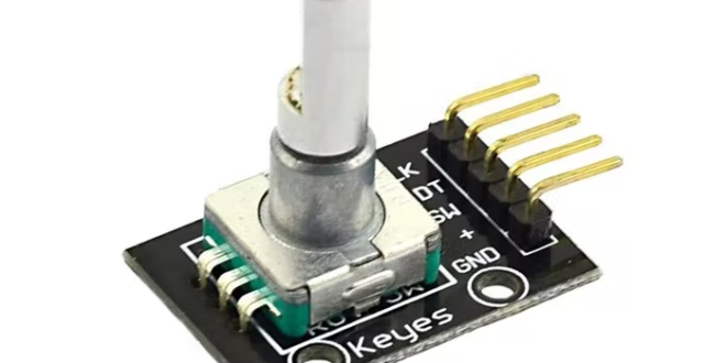
Step 1: Understand the Rotary Encoder
A rotary encoder typically has:
- Two outputs (A and B) that produce pulses as the encoder shaft rotates. The phase difference between these pulses determines the rotation direction.
- A push-button (optional) that can act as an additional input.
Pinout Example (common encoders):
- CLK (A): Clock pulse output
- DT (B): Direction pulse output
- SW: Push-button output
- +: Power (3.3V or 5V)
- GND: Ground
Step 2: Wire the Rotary Encoder to Raspberry Pi
- Power the Encoder:
- Connect the encoder’s + pin to Raspberry Pi's 3.3V pin.
- Connect the GND pin to a Raspberry Pi GND pin.
- Connect the Output Pins:
- Connect the CLK (A) pin to GPIO17 (physical pin 11).
- Connect the DT (B) pin to GPIO18 (physical pin 12).
- Connect the Push Button (if available):
- Connect the SW pin to GPIO27 (physical pin 13).
- Add a pull-down resistor (10kΩ) if necessary.
Step 3: Install Required Libraries
Ensure your Raspberry Pi has Python and GPIO libraries installed:
sudo apt update
sudo apt install python3-rpi.gpio
Step 4: Write the Python Code
Here's an example script to read rotary encoder inputs:
Code:
import RPi.GPIO as GPIO

from time import sleep


# GPIO Pins
CLK = 17
DT = 18
SW = 27  # Optional: Push button

# Setup
GPIO.setmode(GPIO.BCM)
GPIO.setup(CLK, GPIO.IN, pull_up_down=GPIO.PUD_DOWN)
GPIO.setup(DT, GPIO.IN, pull_up_down=GPIO.PUD_DOWN)
GPIO.setup(SW, GPIO.IN, pull_up_down=GPIO.PUD_UP)  # Pull-up for button

# Variables
counter = 0
last_clk = GPIO.input(CLK)

try:
    while True:
        # Read current state of CLK
        current_clk = GPIO.input(CLK)
        current_dt = GPIO.input(DT)

        if current_clk != last_clk:  # Detect a change in CLK
            if current_dt != current_clk:
                counter += 1  # Clockwise
            else:
                counter -= 1  # Counter-clockwise
            print(f"Counter: {counter}")

        last_clk = current_clk

        # Check button press
        if GPIO.input(SW) == GPIO.LOW:
            print("Button pressed!")
            sleep(0.3)  # Debounce delay

        sleep(0.01)  # Small delay to stabilize readings

except KeyboardInterrupt:
    print("\nExiting...")

finally:
    GPIO.cleanup()
Step 5: Run the Script
Save the script as rotary_encoder.py and run it:
python3 rotary_encoder.py
Rotate the encoder and observe the printed values in the terminal. Press the button (if available) to test its functionality.
Step 6: Implement in a Project
Once you've mastered the basics, you can integrate the rotary encoder into projects like:
- Volume controllers
- Menu navigation
- Custom input devices
Tips:
- Debouncing: Rotary encoders might generate false pulses due to mechanical noise. Use software debouncing if needed.
- Interrupts: For real-time response, consider using GPIO interrupts instead of polling.
By following this guide, you can harness the power of a rotary encoder in your Raspberry Pi projects!