
In control systems, a controller corrects the output of a particular system to a target in the presence of errors and disturbances. The most popular type of controller is PID which is an acronym for Proportional, Integral, and Derivative. In this Arduino PID control tutorial, I will show you how you can employ such a controller in your project.
What is PID?
As mentioned, PID is short for proportional, integral, and derivative. The name comes from the methods of how such controllers deal with disturbances in the system. However, such a controller is only in feedback systems. I suggest reading material specifically written for such a topic, but I’ll do my best to explain it here as simply as I can.
A feedback system is one wherein part of the output is “fed back” to the input. For example, you could have a project that controls the fire in the furnace. Below is a simple illustration:
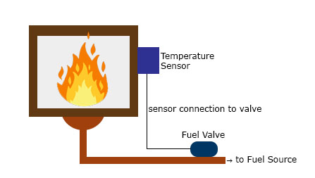
You want to maintain the temperature in the furnace to a certain set point. A temperature sensor in the furnace determines the temperature at any time. This sensor, in this case, provides the feedback as a reference on the required temperature increase or decrease. The difference between the feedback sensor value and a temperature set point is the error.
In this Arduino PID tutorial, we’ll learn how to build a feedback control system that automatically adjusts an actuator such as a motor or heater.
Proportional Control
Proportional control refers to an adjustment that is proportional to how much the error is. Let’s say the controller in our example is an electronic valve for controlling the fuel to the furnace. If the error is small, the valve will release a small amount of fuel so that the set point and the feedback match. If the error is large, the valve must release more fuel.
Integral Control
Proportional control produces offset in its correction due to disturbances. The Integral controller can remove this offset and bring back the error to zero. Such a controller produces an adjustment that is based on the accumulated error over time. Without integral control, the system can’t deal with trends on errors.
Using our previous example, an offset may be present when the fuel valve doesn’t return to its original position when it increases and then decreases its fuel output. The integral controller will detect this and will turn the fuel valve to its original position.
Derivative Control
Finally, Derivative control deals with the rate of change of the error. If integral control looks at the history of the error, derivative control predicts the error. Basically, the amount of correction will be based on how fast the error is changing. This type of controller works best with dynamic errors which both proportional and integral controllers can’t deal with.
Let’s say the temperature in the furnace goes from 130 °C to 140 °C against a 120 °C set point in 2 seconds. The proportional and integral controllers will respond to the magnitude of the error, but they will have a hard time catching up to how fast the error occurred.. The derivative controller can deal with such because it has been looking at the rate of change of the error from the beginning.
A feedback system with a PID controller:
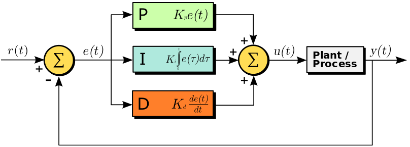

Here the input variable or set point is r(t), the output variable is y(t), the controlled variable is u(t) and the error is e(t). Continuing with our furnace example, r(t) would be the desired temperature and y(t) is the actual temperature; e(t) is the difference between the desired temperature and actual temperature; u(t) is the sum of the corrections from the P, I and D controllers which are fed to the plant which is the fuel valve.
Note that a PID controller is not usable out of the box. Tuning must be done to ensure that the desired performance is achieved. This is done by carefully changing K constants as shown on the diagram above. These constants must be determined beforehand and changed according to the actual response of the system until the optimum values are achieved.
PID Term Effects Overview
This table shows how each PID term typically affects system behavior.
| Term | Response Speed | Offset Removal | Noise Sensitivity |
|---|---|---|---|
| Proportional (P) |
80% |
60% |
50% |
| Integral (I) |
50% |
90% |
60% |
| Derivative (D) |
40% |
40% |
90% |
Implementing PID in Code
To implement a PID controller in an Arduino sketch, we need to calculate the three control terms — Proportional (P), Integral (I), and Derivative (D) — during each loop cycle, based on the error between the setpoint and the actual measured value.
Required Parameters
Before coding, identify these five parameters:
| Parameter | Description |
|---|---|
| Kp | Proportional gain — how strongly the controller reacts to the current error |
| Ki | Integral gain — how strongly it reacts to accumulated error over time |
| Kd | Derivative gain — how strongly it reacts to the rate of error change |
| input | Current measured value (e.g., from sensor or encoder) |
| setPoint | Desired target value |
Step 1: Measure Time Elapsed
PID calculations depend on how much time has passed since the last update.
In Arduino, we can use millis() to get the current runtime in milliseconds.
currentTime = millis();
elapsedTime = currentTime - previousTime;
Step 2: Compute the Error
The error is simply the difference between the target value and the measured value.
error = setPoint - input;
Step 3: Compute the Integral and Derivative
The integral accumulates the total error over time.
The derivative looks at how quickly the error is changing.
cumError += error * elapsedTime;                // Integral term
rateError = (error - lastError) / elapsedTime;  // Derivative term
Tip: Limiting the cumulative error prevents "integral wind-up". You can use constrain(cumError, -maxIntegral, maxIntegral);
Step 4: Combine the Terms to Compute Output
Multiply each term by its constant and sum them to produce the final control output:
output = Kp * error + Ki * cumError + Kd * rateError;
This output can be sent to an actuator (e.g., motor PWM signal, heater power, servo position).
Step 5: Store Current Values for Next Cycle
Before ending the loop, save the latest error and timestamp for the next iteration.
lastError = error;
previousTime = currentTime;
Full Example Code
Below is a simple Arduino PID control loop example for a motor positioning system using a rotary encoder:
// --- PID constants (tune these for your system) ---
double Kp = 2.0;
double Ki = 5.0;
double Kd = 1.0;

// --- PID variables ---
unsigned long currentTime, previousTime;
double elapsedTime;
double error, lastError;
double input, output, setPoint;
double cumError, rateError;

void setup() {
  setPoint = 0; // Target position = 0 degrees
  pinMode(3, OUTPUT);
  Serial.begin(9600);
}

void loop() {
  input = analogRead(A0);        // Read sensor or encoder input
  output = computePID(input);    // Get PID output
  analogWrite(3, output);        // Drive motor (PWM output)
  delay(50);                     // Adjust delay for your system
}

double computePID(double inp) {
  currentTime = millis();
  elapsedTime = (double)(currentTime - previousTime);

  error = setPoint - inp;
  cumError += error * elapsedTime;
  rateError = (error - lastError) / elapsedTime;

  double out = Kp * error + Ki * cumError + Kd * rateError;

  // --- Prevent integral wind-up ---
  out = constrain(out, 0, 255);

  lastError = error;
  previousTime = currentTime;

  return out;
}
Understanding the Output
- Increasing Kp makes the system respond faster but can cause oscillation.
- Increasing Ki helps reach the target value by removing steady-state error.
- Increasing Kd reduces overshoot and stabilizes the response.
Try printing the values to the Serial Monitor:
Serial.print("Error: "); Serial.print(error);
Serial.print("\tOutput: "); Serial.println(output);
This helps you visualize the controller’s performance while tuning.
If you prefer not to write your own PID logic, you can use Brett Beauregard’s PID_v1 library — which includes automatic handling of timing, limits, and modes. Let’s explore that next.
Using the Arduino PID Library
Manually coding a PID loop is a great learning exercise, but for most projects it’s easier and safer to use the Arduino PID Library written by Brett Beauregard.
This library (known as PID_v1) takes care of timing, output limits, and direction — letting you focus on tuning and testing instead of math.
Installing the Library
1. In the Arduino IDE, go to Sketch → Include Library → Manage Libraries…
2. Search for “PID”
3. Install “PID by Brett Beauregard”
4. Once installed, include it in your sketch:
#include <PID_v1.h>
How It Works
You define:
- Input — the process variable (e.g., temperature, position)
- Setpoint — the target value
- Output — the control signal sent to the actuator (PWM, valve, etc.)
- Tunings — constants Kp, Ki, Kd
The library continuously computes:
Output = Kp * error + Ki * integral + Kd * derivative
at a set sample rate (default: 100ms).
Basic Example
Below is the classic PID_Basic.ino example that ships with the library. This sketch controls an analog input (like a temperature or position sensor) and writes the PID output to a PWM pin.
#include <PID_v1.h>

#define PIN_INPUT  A0
#define PIN_OUTPUT 3

// --- Define Variables we’ll be connecting to ---
double Setpoint, Input, Output;

// --- Specify initial tuning parameters ---
double Kp = 2, Ki = 5, Kd = 1;

// Create PID object: (Input, Output, Setpoint, Kp, Ki, Kd, Direction)
PID myPID(&Input, &Output, &Setpoint, Kp, Ki, Kd, DIRECT);

void setup() {
  Serial.begin(9600);
  Setpoint = 100;              // Target value
  Input = analogRead(PIN_INPUT);
  myPID.SetMode(AUTOMATIC);    // Enable PID
  myPID.SetOutputLimits(0, 255); // Limit PWM output range
}

void loop() {
  Input = analogRead(PIN_INPUT);  // Read process variable
  myPID.Compute();                // Calculate PID output
  analogWrite(PIN_OUTPUT, Output); // Drive actuator

  Serial.print("Input: "); Serial.print(Input);
  Serial.print("\tOutput: "); Serial.println(Output);
  delay(100);
}
Key Library Functions
| Function | Purpose | Example |
|---|---|---|
| Compute() | Runs one PID calculation cycle | myPID.Compute(); |
| SetMode(AUTOMATIC / MANUAL) | Turns the controller on/off | myPID.SetMode(AUTOMATIC); |
| SetTunings(Kp, Ki, Kd) | Updates PID constants on the fly | myPID.SetTunings(2.5, 4.0, 1.2); |
| SetSampleTime(ms) | Changes how often PID runs | myPID.SetSampleTime(50); |
| SetOutputLimits(min, max) | Prevents integral wind-up / actuator saturation | myPID.SetOutputLimits(0, 255); |
| SetControllerDirection(DIRECT / REVERSE) | Flips control direction (useful for inverted systems) | myPID.SetControllerDirection(REVERSE); |
Manual vs. Library Approach
| Aspect | Manual Code | Using PID_v1 Library |
|---|---|---|
| Timing | You must track millis() manually | Handled internally |
| Integral wind-up | You must constrain manually | Automatically handled |
| Output limits | Manual constrain() | Built-in via SetOutputLimits() |
| Direction control | Manual sign flipping | SetControllerDirection() |
| Ease of tuning | Requires more math | Simplified via function calls |
| Best for | Learning / full control | Real projects needing stability |
Tuning with the Library
Start with:
double Kp = 2, Ki = 5, Kd = 1;
Then:
- Increase Kp until the output starts oscillating.
- Slowly increase Ki to eliminate steady-state error.
- Add Kd to smooth the response.
Optional:
myPID.SetSampleTime(50); // faster updates (50 ms)
myPID.SetOutputLimits(0, 255); // match your actuator range
Tip: For slow systems like temperature control, use a longer sample time (500–1000 ms).
For fast systems (motor speed), shorter intervals (20–100 ms) work better.
Advanced: Auto-Tuning PID
You can add the PID_AutoTune library by the same author to find near-optimal constants automatically.
It works by oscillating the system and calculating Kp, Ki, and Kd based on response data.
Once tuned, hardcode those values for stable operation.
- The PID library simplifies everything — you just define input, output, setpoint, and constants.
- Use SetOutputLimits() and SetMode() to prevent overshoot and actuator strain.
- Combine this with real sensor feedback (e.g., temperature, distance, position) for stable closed-loop control.
Next: Try combining this with the PID Tuning Example section to visualize how each constant affects your Arduino project.
PID Tuning Example
To see PID control in action, let’s apply it to a simple temperature control system.
Hardware Setup
- Arduino Uno or compatible board
- LM35 or TMP36 temperature sensor
- MOSFET or relay to switch a heating element (small lamp or resistor)
- 5V power supply
- Serial Monitor to observe temperature readings
The goal is to maintain the temperature at 40 °C using PID.
Step-by-Step
- Start with Kp only (Ki = 0, Kd = 0).
Increase Kp gradually until the temperature oscillates around the setpoint.
This finds the “critical” proportional gain. - Add Ki slowly to remove steady-state error.
If the system overshoots or reacts sluggishly, reduce Ki. - Add Kd to dampen overshoot and make the response smoother.
Kd predicts rapid changes in error.
Example parameter set (your results will vary):
| Parameter | Description | Example Value |
|---|---|---|
| Kp | proportional gain | 2.0 |
| Ki | integral gain | 0.5 |
| Kd | derivative gain | 1.0 |
| Setpoint | desired temperature | 40 °C |
Observing the Response
Below is a sample plot of the system’s step response while tuning:
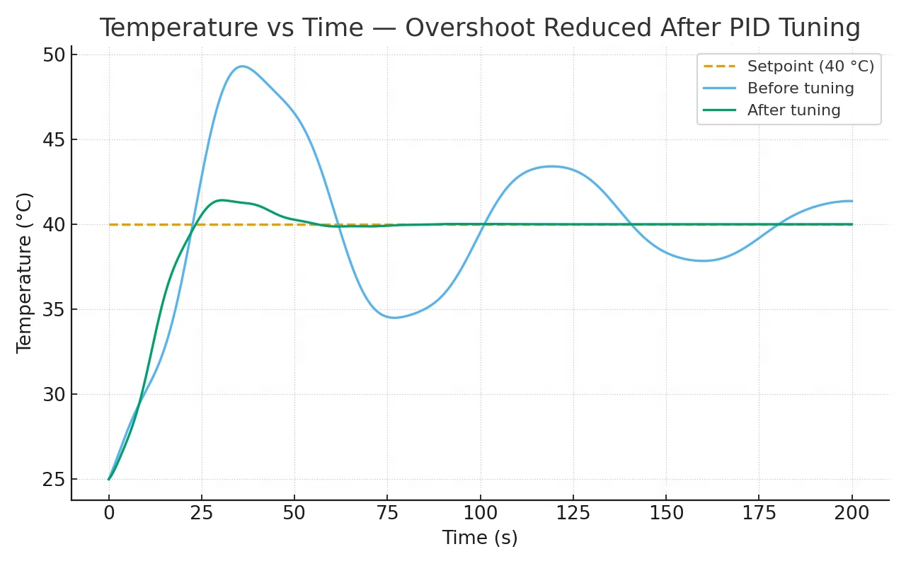
You should see:
- Faster rise time with increasing Kp
- Reduced offset with Ki
- Minimal overshoot with correct Kd
Code Snippet
You can adapt your earlier sketch by printing values to the Serial Monitor:
Serial.print("Temp: ");
Serial.print(Input);
Serial.print("  Output: ");
Serial.println(Output);
Then log these readings into Excel or Plotter to visualize PID performance.
Tip: For slower systems (like temperature), choose a longer sample time (e.g., 1 second). For faster systems (motors), use shorter intervals (10–100 ms).
Troubleshooting and FAQs
Even with correct formulas, PID tuning can be tricky.
Here are some common issues and fixes you can try:
Q: My output oscillates rapidly.
A: Your Kp is too high or loop interval is too short.
→ Reduce Kp gradually or add a small Kd term to stabilize.
Q: The system reacts slowly and never reaches the setpoint.
A: Increase Kp slightly or raise Ki to remove the steady-state error.
Make sure your actuator (motor, heater, etc.) is powerful enough.
Q: My integral term keeps increasing (system overshoots badly).
A: This is integral wind-up.
Use the PID library’s SetOutputLimits() function to restrict the output range, or reset the integral when output saturates.
Q: The derivative term makes my output noisy.
A: Add a small delay or filter your input sensor value.
Derivative amplifies noise, so a simple moving average helps.
Q: Can I use this PID library on an ESP32 or STM32 board?
A: Yes. The PID_v1 library is platform-independent.
Just adjust PWM resolution and output limits for your microcontroller.
Q: How do I choose the right sample time?
A: As a rule of thumb, pick a loop interval 5–10 × faster than your system’s expected response time.
For motors: 50–100 ms; for temperature control: 1–2 s.
Summary and Closing
When tuning:
- Start with Kp only → find a stable oscillation.
- Add Ki to remove offset.
- Add Kd to smooth response.
- Use small incremental adjustments and record your results.
Tip: Patience matters — even small parameter changes can have a big effect on control stability
Hopefully, you have a slight grasp of how to implement PID control in this article. It is a powerful controller that will reduce manual correction for your systems. If you have any questions about implementing Arduino PID, kindly drop a comment below!


")


for the code you provided and not the library , where do i write the value of my setpoint?
How to implement PID temperature control for MLX90614 IR sensor which gives reading I2C.
Hi,
Get the temperature data and make it an input to the PID. The output of the PID is then used to control whatever that is generating heat on your project
I WANT TO CONNECT A FAN IN CASE MY TEMP IS LESSER THAN THE SET POINT.WHAT CHANGING I SHOULD DO
Hi, I'm trying to balance a robot with one wheel using a stepper motor and accelerometer data that gives me current angle ... How can I implement the PID controller?
Hello,
The basic idea would be that the input to your PID is the current angle of the robot while the output is the number of steps the stepper motor needs to move to counteract the offset of the robot. I’ve actually done a self balancing robot before but it was done using dc motors so I cant give anything more specific for your case.
hello can i get the code for the self balancing robot? my robot would not give a feedback when it is turned on.
In your PID implementation (not the library) you use lastError before assignment, you should probably assign it a default value in setup just to be safe.
Hi,
My project is to control an actual which elongates by inflating or deflating air into. An amount of air is controlled by a velocity of air_pump. A distance is measured by a proximity sensor. So how can I use a PID algorithm to control the velocity of the air-pump, which is used to manipulate the actuator to a setpoint, based on a feedback value from the proximity sensor?
I have no idea about PID things. can you explain how could you get the value of KP, KI, and KD
Hi, nice explanation, thanks for that. I'm dealing with the following: in order to fire up (bake) ceramics, i need to gradually increase the temperature (let's say, going up to 650°C in about 6 hours). I like to use PID control to keep the temperature as close to the desired temperature as possible (on that point in time) but since i have to change (increase) the temperature gradually, the "set point" will keep changing over time. Do you think this would be possible? Raising the "set point" would result in an detected error thus "confusing" the derivative control, right? Or am i overthinking this a bit? 🙂 Thanks again. Cheers. p
Hi,
That’s a good question. Actually, PID controller works with variable set points, as long as the variation is not random. Your example of gradually changing the set point temperature is a ramp type input, a common type of input in control systems. In your case, the error continuously changes because of the variation for both set point and actual temperature. The derivative term will deal with how fast that error is changing so there’s no problem there.
Thank you for your answer, Roland! I'll give it a shot.
Hi,
I am trying to build a differential drive robot(DDR) with DC motors with Arduino. The problem is that the built DDR does not move in a straight line because the two motors run at different speeds for the same input given by Pulse width Modulation.
Now, I had a plan to implement the PID controller in Arduino to control the DC motor. or to use a stepper motor or to use a Servo motor. Kindly give your opinion regarding this.
Thank you
How to determine the values of Kd, Kp, Ki??
Hello,
Thanks for the code. On this line:
analogWrite(3, output); //control the motor based on PID value
What is the 3 for?. Does it mean Pin 3?. Would it not have to be also defined as A3 or B1 or C0...etc??
On the other hand a ";" is missing after every PID constant at the beginning. "setpoint" is written with different capital letters. Just thought I would mention it for those who struggle because of those details detail.
https://playground.arduino.cc/Code/PIDAutotuneLibrary/
Hi,
To calculate the integral and derivative error, shouldn't we use the elapsed time in seconds instead of milliseconds?
I mean, dividing elapsedTime by 1000?
Is it possible to do multiple PID loop in single arduino code?
Very clear explanations.
This article is the best I have found on the Internet today.
Thanks a lot for the time you spend on this for us 😉
can you help me how to make coding to robot path tracer?i'm a newer for robotics project in my school
hi, assuming I have a 0 knowledge in PID, but were tasked to make a color sorter using PID in arduino, how do i code it and what are the tips or information i need to know? thankyou
hi, im trying to use PID library for a DC/DC boost converter but i kind confuse how to implement it.
when the dc motor reaches the specified set point the motor must stop. ie: the output must become zero, but if we use integral , when the error becomes zero, the cumulative error is still non zero thus making the output non zero hence the motor would still continue to run even after the set point is achieved. Correct me if I am wrong.
please how can implement PID controller with DHT sensor and dc fan motor
Hi,
I assume that your input is temperature and output is the current to the fan. You need to establish a numerical relationship between the temperature and how much current is needed to drive the fan.
Hi there, I have been trying to implement PID for regulating a PDLC film on the basis of temperature, I am using an ESP32 instead of an arduino. I am facing some problems with how to implement the same. Would be happy for your input
Hi,
I saw lot of videos about self balancing robots and I would like to build one. For this purpose I would use MPU-6050 and 2 DC motor with L298N motor driver and one Arduino Nano. I study vehicle engineering so I may say it is a little familier to me 😀 but also I could understand far better the concept if I could implement the PID algorithm. I know it would be easier to copy one of the solutions on the net but I want to do it for myself.
In previous comments I read You also bulit slef balancing robot. I would highly appreciate if You could help me and share some information and knowledge with me of your project. How you did it and what helped you to understand this?
Thanks in advance:)
Archi
Hi,
This might be too late of a reply, but you can check the source code for my self-balancing robot here: https://github.com/kurimawxx00/arduino-self-balancing-robot
Pictures of the setup is here: https://hackaday.io/project/21920-ambot
Haha - bunch of folks who want you to write their code for them.
Thanks for the simple explanation.
Im trying to control an rlc circuit system with aurdino as an pid controller. I would like to know if I can give the variable set point to aurdino and how the output of aurdino be connected to be as in input to rlc circuit
Also can the aurdino be configured in discrete controller
Please send me the circuit diagram/schematic of temperature furnace.
the links have been Hacked and don't link to the expected material.
"list of function" and "limitations of PID"