

Plants need more than water to grow well. They also need nutrients in the soil, especially nitrogen, phosphorus, and potassium. These three nutrients are often shortened to NPK, which is why this type of soil nutrient probe is commonly called an NPK sensor.
In this tutorial, you will learn how to use an NPK sensor with Arduino through an RS485 transceiver module. We will look at how the sensor works, how to wire it to an Arduino UNO, and how to request nitrogen, phosphorus, and potassium readings using Arduino code.
What Does an NPK Sensor Measure?
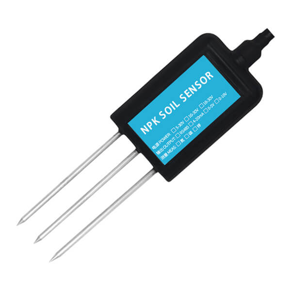
An NPK sensor measures the amount of nitrogen, phosphorus, and potassium in soil. These three nutrients affect plant growth in different ways:
- Nitrogen helps plants grow leaves and stems.
- Phosphorus supports root development, flowering, and fruiting.
- Potassium helps the plant regulate water, resist stress, and improve overall health.
Because of this, farmers, gardeners, and plant monitoring systems use NPK readings to estimate soil fertility. However, low-cost sensors should be treated as practical field sensors, not laboratory instruments. For best results, compare their readings with a known soil test and adjust your code or interpretation if needed.
Types of NPK Sensors
NPK sensors can use different sensing methods. The three common types are optical, electrochemical, and conductive.
Optical NPK Sensors
Optical sensors analyze how light behaves when it passes through soil or a prepared soil sample. Different nutrient concentrations affect how the sample absorbs or reflects light. These sensors can be accurate, but they usually cost more and may need careful calibration.
Electrochemical NPK Sensors
Electrochemical sensors use chemical reactions or special transistor-based sensing elements to detect nutrient ions. These sensors can target specific chemicals more directly, but they also tend to require better calibration and more controlled measurement conditions.
Conductive NPK Sensors
Conductive sensors use metal electrodes inserted into the soil. The sensor sends a small electrical signal through the soil and measures conductivity. Since dissolved nutrient ions affect conductivity, the sensor estimates the amount of nitrogen, phosphorus, and potassium from the measured response.
This tutorial focuses on the conductive type because it is common, affordable, and often sold with an RS485 interface.
How a Conductive NPK Sensor Works
A conductive soil nutrient sensor has a metal probe that you insert into the soil. When the probe touches moist soil, the electrodes interact with the soil solution. The sensor then measures electrical conductivity and converts that measurement into nutrient values.
Most low-cost modules do not output a simple analog voltage. Instead, they use a digital communication interface, usually RS485. The sensor waits for a command from a master device. After receiving the correct command, it sends back a response containing the requested nutrient value.
In this project, the Arduino acts as the master device. The soil sensor acts as the slave device.
Why the Sensor Uses RS485
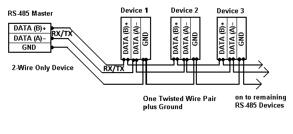
RS485 is a serial communication standard used in industrial and outdoor systems. It works well over longer cable distances and handles electrical noise better than ordinary TTL serial communication.
RS485 uses differential signaling. Instead of using one signal wire referenced to ground, it uses two communication lines, usually labeled A and B. This makes RS485 more reliable for sensors placed away from the controller.
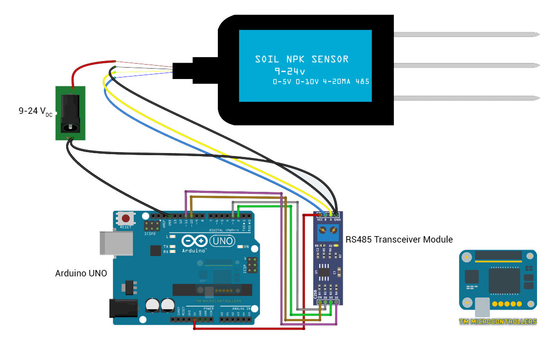
An Arduino UNO cannot connect directly to RS485 lines. Its serial pins use TTL-level UART signals. Therefore, you need an RS485-to-TTL transceiver module, such as a MAX485 module, between the Arduino and the soil sensor.
![]()
Parts Required
For this project, you need:
- Arduino UNO or compatible board
- RS485-to-TTL transceiver module
- NPK soil sensor with RS485 output
- External DC power supply for the sensor
- Jumper wires
- USB cable for programming the Arduino
Check your sensor label or datasheet before wiring the power supply. Many soil NPK probes need 9 V to 24 V DC. Do not power this type of probe from the Arduino 5 V pin unless the datasheet clearly says it supports 5 V operation.
Arduino to RS485 Module Wiring
Connect the RS485 transceiver module to the Arduino as follows:
| RS485 Module Pin | Arduino UNO Pin |
|---|---|
| VCC | 5V |
| GND | GND |
| DI | D11 |
| RO | D10 |
| DE | D2 |
| RE | D3 |
The DI pin receives data from the Arduino transmit pin. The RO pin sends data to the Arduino receive pin. The DE and RE pins control whether the transceiver is transmitting or receiving.
RS485 Module to NPK Sensor Wiring
Connect the RS485 side of the transceiver module to the sensor:
| RS485 Module Pin | Sensor Wire / Terminal |
|---|---|
| A | A / TX+ / RS485+ |
| B | B / TX- / RS485- |
| GND | Sensor ground, if required |
| Sensor VCC | External 9-24 V DC supply |
| Sensor GND | External supply ground |
Some modules label the RS485 lines as A and B, while others use TX+ and TX-. If you do not receive data, try swapping A and B. Many wiring problems with RS485 sensors come from reversed differential lines.
How the Arduino Requests NPK Data
Most RS485 soil nutrient sensors use Modbus RTU-style commands. The Arduino sends a request frame to the sensor. The sensor then replies with a frame containing the measured value.
A typical request contains:
- Sensor address
- Function code
- Register address
- Number of registers to read
- CRC checksum
For many common NPK probes, the command for nitrogen, phosphorus, and potassium uses function code
0x03The example commands below request one register for each nutrient:
const byte nitro[] = {0x01, 0x03, 0x00, 0x1E, 0x00, 0x01, 0xE4, 0x0C};
const byte phosp[] = {0x01, 0x03, 0x00, 0x1F, 0x00, 0x01, 0xB5, 0xCC};
const byte potas[] = {0x01, 0x03, 0x00, 0x20, 0x00, 0x01, 0x85, 0xC0};
These commands may vary depending on your sensor model. Always check the datasheet that came with your sensor.
Arduino Code for Reading NPK Values
Upload this sketch to the Arduino UNO:
#include <SoftwareSerial.h>

#define DE_PIN 2
#define RE_PIN 3

SoftwareSerial RS485Serial(10, 11); // RX, TX

const byte nitro[] = {0x01, 0x03, 0x00, 0x1E, 0x00, 0x01, 0xE4, 0x0C};
const byte phosp[] = {0x01, 0x03, 0x00, 0x1F, 0x00, 0x01, 0xB5, 0xCC};
const byte potas[] = {0x01, 0x03, 0x00, 0x20, 0x00, 0x01, 0x85, 0xC0};

byte nitroValue;
byte phospValue;
byte potassValue;

byte responseBuffer[7];

void setup() {
  Serial.begin(9600);
  RS485Serial.begin(9600);

  pinMode(DE_PIN, OUTPUT);
  pinMode(RE_PIN, OUTPUT);

  receiveMode();

  Serial.println("NPK Sensor Reading Started");
}

void loop() {
  nitroValue = readNutrient(nitro, sizeof(nitro));
  delay(250);

  phospValue = readNutrient(phosp, sizeof(phosp));
  delay(250);

  potassValue = readNutrient(potas, sizeof(potas));
  delay(250);

  Serial.print("Soil N: ");
  Serial.print(nitroValue);
  Serial.println(" mg/kg");

  Serial.print("Soil P: ");
  Serial.print(phospValue);
  Serial.println(" mg/kg");

  Serial.print("Soil K: ");
  Serial.print(potassValue);
  Serial.println(" mg/kg");

  Serial.println();
  delay(2000);
}

void transmitMode() {
  digitalWrite(DE_PIN, HIGH);
  digitalWrite(RE_PIN, HIGH);
}

void receiveMode() {
  digitalWrite(DE_PIN, LOW);
  digitalWrite(RE_PIN, LOW);
}

byte readNutrient(const byte request[], byte requestSize) {
  transmitMode();
  delay(10);

  RS485Serial.write(request, requestSize);
  RS485Serial.flush();

  receiveMode();
  delay(100);

  for (byte i = 0; i < 7; i++) {
    if (RS485Serial.available()) {
      responseBuffer[i] = RS485Serial.read();

      Serial.print(responseBuffer[i], HEX);
      Serial.print("\t");
    }
  }

  Serial.println();

  return responseBuffer[4];
}
How the Code Works
The sketch uses SoftwareSerial so the Arduino can communicate with the RS485 module through pins 10 and 11. This leaves the hardware serial port available for the Serial Monitor.
The DE_PIN and RE_PIN control the direction of the RS485 transceiver. When both pins go HIGH, the module transmits data. When both pins go LOW, the module receives data.
The Arduino sends one request for nitrogen, one for phosphorus, and one for potassium. After each request, it waits for the sensor response and reads the returned bytes.
In the example response, the nutrient value appears in the fifth byte of the response frame, which is index 4 in the buffer. The sketch prints that value in mg/kg.
Understanding the Sensor Response
A typical response from the sensor contains several bytes. These bytes include the sensor address, function code, number of data bytes, nutrient value, and CRC checksum.
For example, if the sensor returns a value of 0x30, the decimal equivalent is 48. Therefore, the nutrient reading is 48 mg/kg.
If your sensor returns larger values, it may use two bytes for the reading. In that case, combine the high byte and low byte like this:
int value = (responseBuffer[3] << 8) | responseBuffer[4];
Check your sensor datasheet to confirm the correct byte order and register format.
Troubleshooting No Readings
If the Serial Monitor only shows zeros, random values, or no response, check these common issues first:
- Make sure the sensor receives the correct external supply voltage.
- Connect all grounds together if your module requires a common reference.
- Try swapping the RS485 A and B wires.
- Confirm that the baud rate matches the sensor datasheet.
- Check the sensor address in the command frame.
- Make sure DE and RE switch back to receive mode after transmitting.
- Insert the probe into moist soil, not dry soil.
- Use the correct Modbus command for your exact sensor model.
RS485 sensors are sensitive to wiring and command format. If the wiring looks correct but the sensor still does not reply, the command registers may not match your particular model.
Using an NPK + pH + Moisture Sensor
Some soil sensors measure more than nitrogen, phosphorus, and potassium. A 5-in-1 sensor may also measure soil pH and moisture.
These sensors usually use the same RS485 wiring, but they require additional Modbus commands for the extra values. The pH and moisture readings often come from different register addresses.
Before adding pH and moisture to the Arduino sketch, get the complete command table from your sensor datasheet. Then add new request arrays, call the same
readNutrient()Frequently Asked Questions
What is an NPK sensor?
An NPK sensor measures nitrogen, phosphorus, and potassium levels in soil. These readings help estimate soil fertility and guide plant care or fertilizer decisions.
How does an NPK sensor work with Arduino?
Most low-cost probes use RS485 communication. The Arduino sends a command through an RS485 transceiver module, then reads the response from the sensor.
Can I connect an NPK sensor directly to Arduino?
Usually, no. Most RS485 soil sensors need an RS485-to-TTL transceiver module. The Arduino uses TTL serial, while the sensor uses RS485 differential signaling.
Which Arduino boards can read an NPK sensor?
You can use an Arduino UNO, Nano, Mega, or other compatible board. A Mega is easier for serial projects because it has extra hardware serial ports, but an UNO also works with
SoftwareSerialCan I use more than one sensor?
Yes, RS485 supports multiple devices on the same bus. However, each sensor must use a different Modbus address. You also need to send commands to the correct address.
How accurate are low-cost NPK sensors?
Low-cost soil nutrient sensors provide approximate readings. Moisture, soil type, temperature, calibration, and sensor quality can affect the result. For critical agricultural decisions, compare the readings with laboratory soil tests.
Do I need to calibrate the sensor?
Many sensors come factory-calibrated, but calibration can improve your results. You can compare the sensor reading with a known soil test and apply a correction factor in your Arduino code.
Some sensors come factory-calibrated, but you can improve accuracy by comparing readings with known soil test results and applying correction factors in code.


