
Have you read the MAX30100 tutorial and are still having trouble making that chip work? Maybe it’s time to use another Arduino heart rate sensor. The MAX30102 module has a better hardware design and software support. I’ll explain why after the jump.
How Does MAX30102 Detect Heart Rate
From MAX30100 Tutorial:
"The device has two LEDs, one emitting red light, another emitting infrared light. For pulse rate, only infrared light is needed. Both red light and infrared light are used to measure oxygen levels in the blood.
When the heart pumps blood, there is an increase in oxygenated blood as a result of having more blood. As the heart relaxes, the volume of oxygenated blood also decreases. Ultimately, by knowing the time between the increase and decrease of oxygen-rich blood, the device calculates the pulse rate.
It turns out, oxygenated blood absorbs more infrared light and passes more red light while deoxygenated blood absorbs red light and passes more infrared light. This is the main function of the MAX30102: it reads the absorption levels for both light sources and stores them in a buffer that can be read via I2C."
MAX30100 vs MAX30102
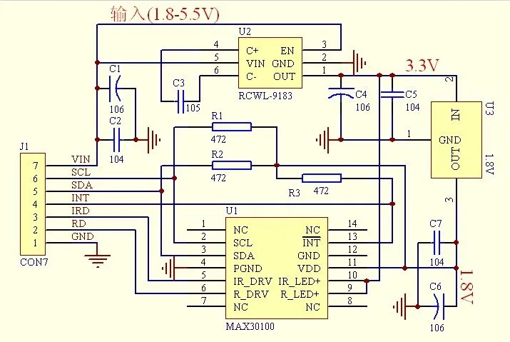
To be clear, the MAX30100 integrated circuit works, the problem is the design of the RCWL-0530 module where it’s mounted. The error lies in the I2C pull-up resistors being connected to 1.8 V. This is too low of a voltage for an Arduino to detect.
Below is the schematic of the RCWL-0530. The I2C pull-up resistors are R1 and R2 and you can trace them to the 1.8 V line.
The RCWL-0531, which now features the MAX30102, fixes this defect by adding a pad for selecting the correct voltage for the pull-ups:
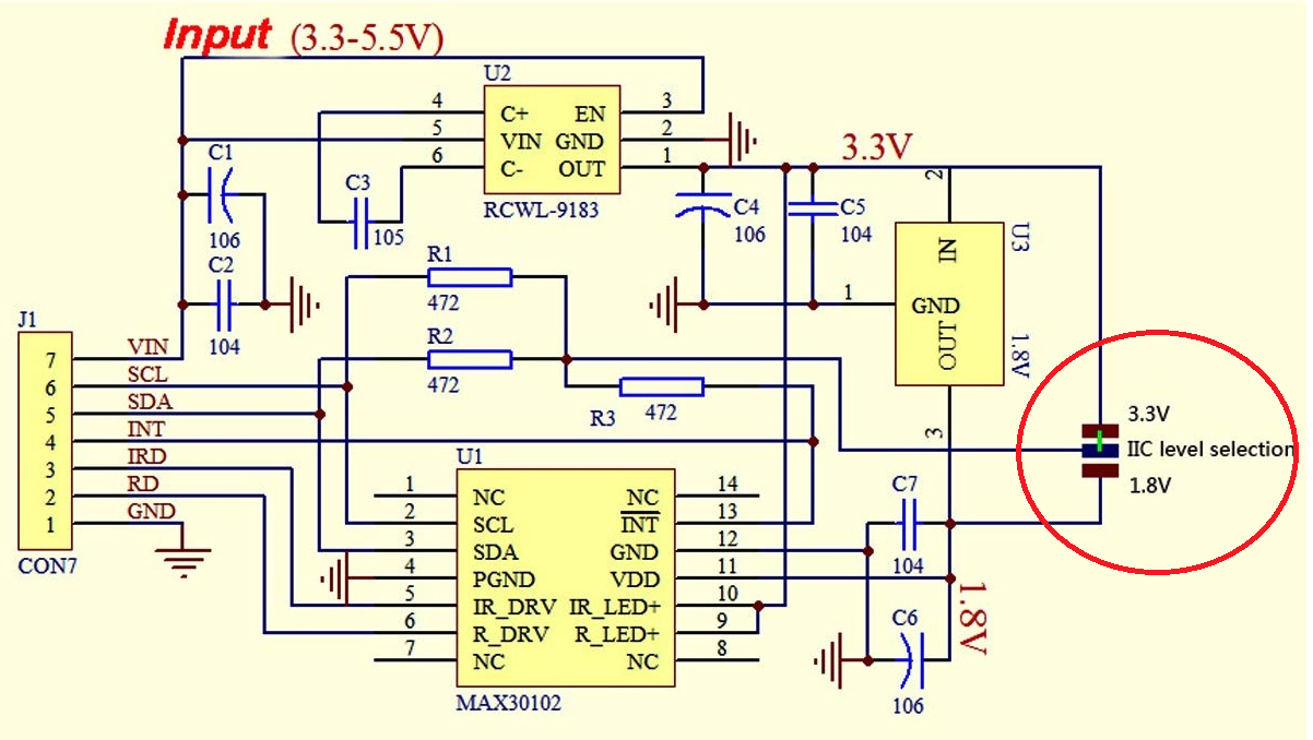
The voltage is at 3.3 V by default, now compatible with logic levels for Arduino. This means there’s no need to hack anything on the RCWL-0531 module!
Aside from the improvements in the module, there are also other things where the MAX30102 trumps the MAX30100:
- 32-bit vs 16-bit FIFO - the MAX30102 has higher storage for data yet to be transferred to the microcontroller, resulting in a faster data transfer
- 18-bit vs 16-bit ADC resolution - the MAX30102 is more sensitive to changes in IR receiver voltage
- 69 us-114 us vs 200 us-1.6 ms LED pulse width - the MAX30102 has a narrower LED pulse width, resulting in lower power consumption
These things justify the slight price increase on the MAX30102 vs MAX30100.
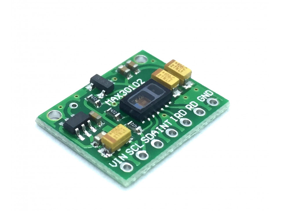
The RCWL-0531 MAX30102 module comes in a green-colored board (very much similar to the RCWL-0530 MAX30100):
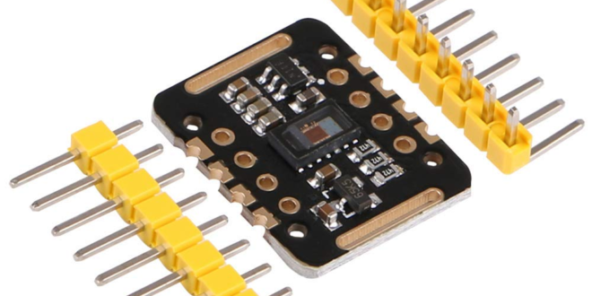
A variant is a black-colored board that includes voltage level shifters: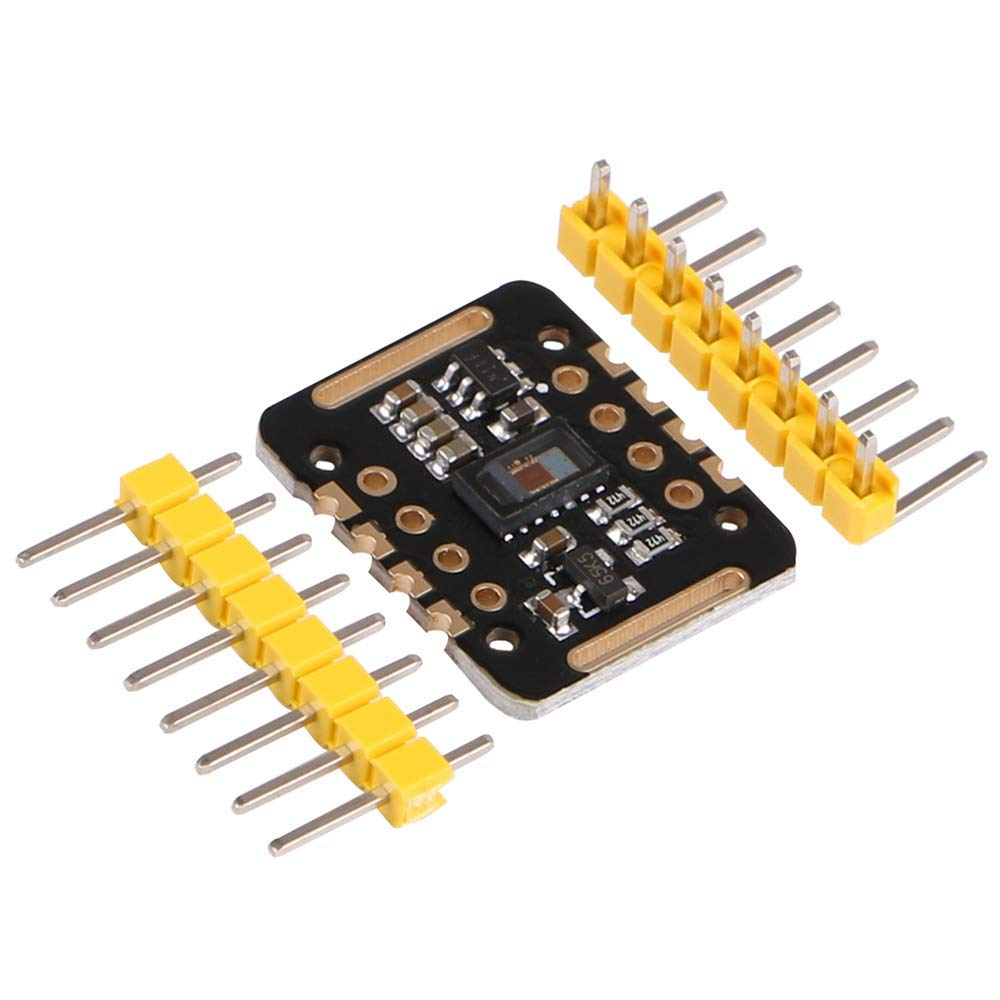
I own both the black and green ones though I prefer the latter because I can safely wire it directly to the Arduino without worrying about converting logic voltages.
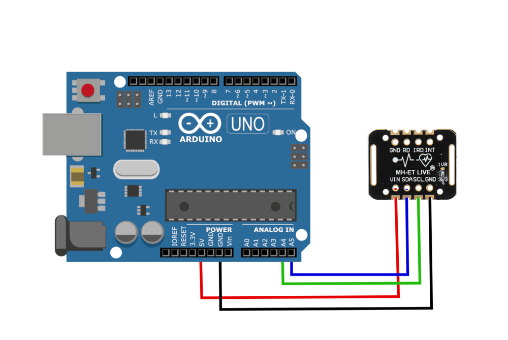
Using the MAX30102 with Arduino
The MAX30102 communicates via I2C, so to use the black model with an Arduino, just connect it like any other I2C device. However, the green model uses 3.3 logic levels and so you'll need to have logic level shifters to safely use it with Arduino.
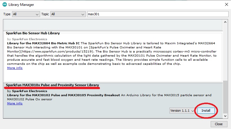
Next, you need to download Sparkfun’s MAX30102 library. This library only works for the MAX30102 (and the advanced MAX30105) and I can say it's much better than the MAX30100 libraries. You can clone the library here or use the Arduino IDE’s library manager (Sketch > Include Library > Manage Libraries or CTRL+SHIFT+I for Windows).
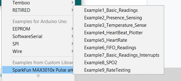
You could start off with any of these examples for your project.
Here's the output for the sketch which simply displays data on the serial monitor.
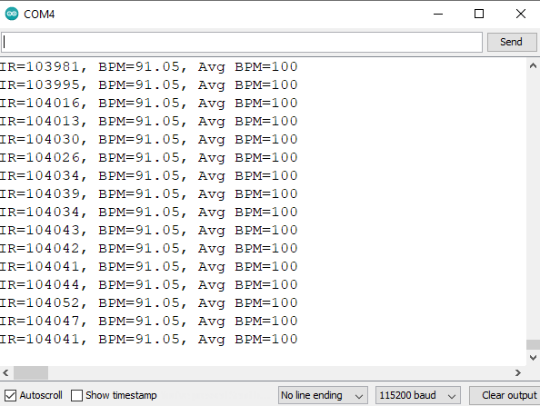
Note that it takes almost a minute or so before the MAX30102 has stable readings.
Arduino Heart Rate Monitor Project
I modified the Example5_HeartRate sketch, and then added a 1.8” TFT display where the BPM and a little beating heart are displayed.
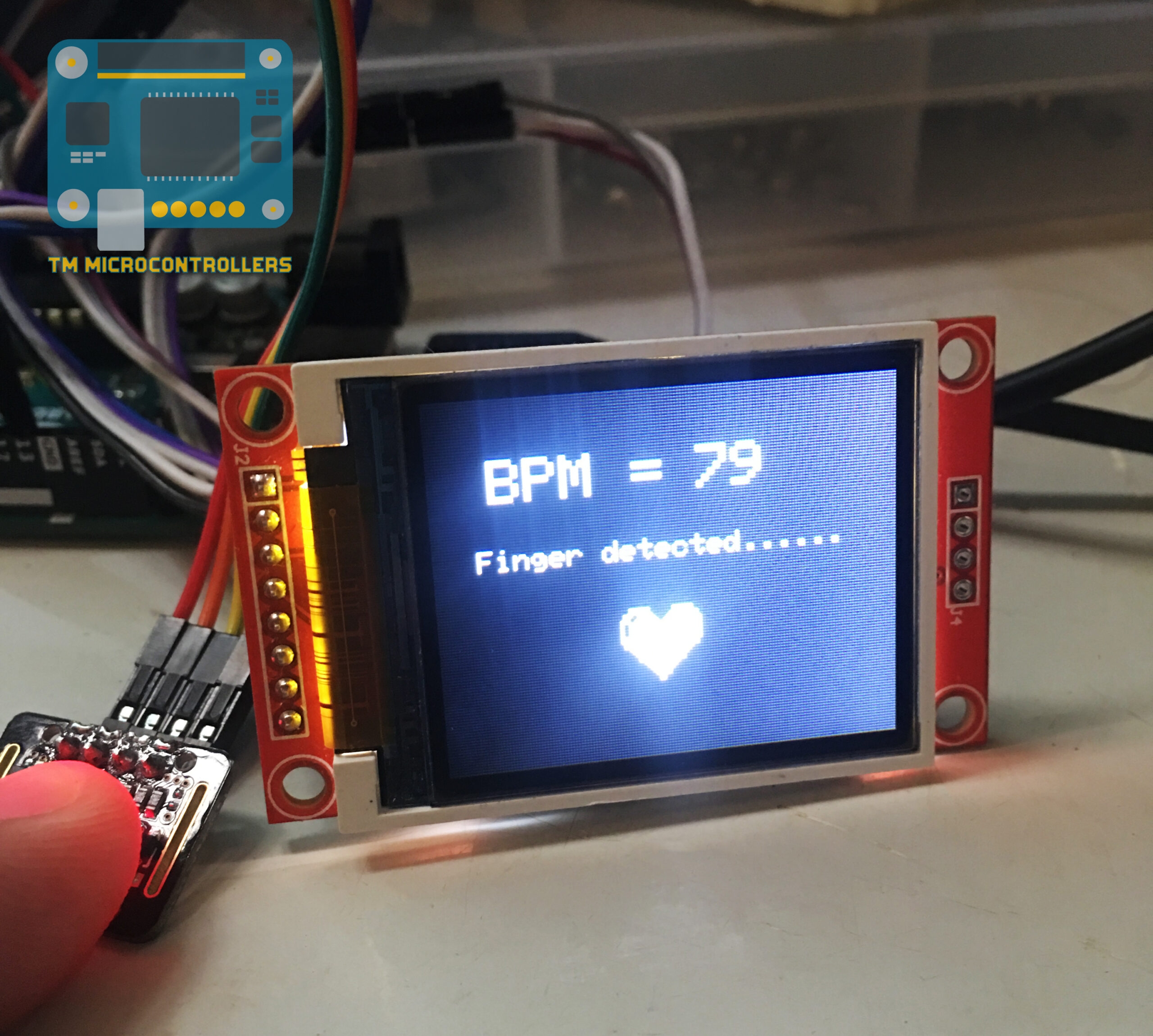
The heart icon beats according to the heart rate read by the sensor. Details of this project will be in a separate post.


Don't we need a logic converter to connect the 3.3v max30102 to the 5v arduino i2c?
Max30102 I2C has voltage levels at: Lv = 0-0.6 and Hv = 1.4-1.8, according to the data sheet:
https://www.alldatasheet.com/view.jsp?Searchword=Max30102
We just have to put a logical level converter, such as:
https://www.sparkfun.com/products/12009
Between the max30102 SCL and SDA pins (logic level 1.8v) and the arduino (5v) pins.
To get a reference for the logic converter at 1.8v we can use a voltage divider from the arduino Vcc=5v with a 1kohm and 560 ohm resistors.
I tried this with an arduino uno.