
The moment I got my hands on the MAX30100 breakout board, I was ready to create my own Arduino heart rate sensor. But building one wasn’t as easy as I thought.
Introduction
Having problems with this sensor module? Consider changing to the MAX30102, as it's Arduino-ready in both hardware design and software library.
First, let me try to explain how the MAX30100 measures pulse rate. The device has two LEDs, one emitting a red light, another emitting infrared light. For pulse rate, only the infrared light is needed. Both the red light and infrared light is used to measure oxygen levels in the blood. More on that later.
When the heart pumps blood, there is an increase in oxygenated blood as a result of having more blood. As the heart relaxes, the volume of oxygenated blood also decreases. Ultimately, by knowing the time between the increase and decrease of oxygen-rich blood, the device calculates the pulse rate.
It turns out, oxygenated blood absorbs more infrared light and passes more red light while deoxygenated blood absorbs red light and passes more infrared light. This is the main function of the MAX30100: it reads the absorption levels for both light sources and stored them in a buffer that can be read via I2C.
But again it's not as simple as it sounds, there’s a lot of data filtering involved like how this awesome post shows.
The Simple MAX30100 Arduino Module
Now let’s create a heart rate monitor where the values are displayed through the serial port.
There are two widely available MAX30100 breakout boards in the market. If you have the GY-MAX30100 board:
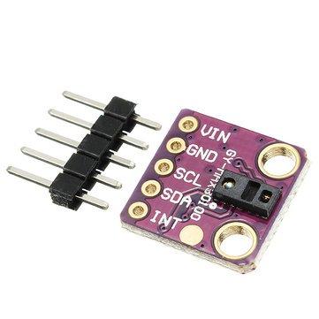
Then lucky you! This board is ready for use with an Arduino. Just follow this wiring setup:
| Purple MAX30100 Module | Arduino UNO/Nano |
| VIN | 5V |
| GND | GND |
| SCL | A5 |
| SDA | A4 |
| INT | D2 |
Just follow this wiring setup and use Raivis Strogonovs MAX30100 library. The library is quite easy to use; here’s an example sketch:
#include "MAX30100.h"

MAX30100* pulseOxymeter;

void setup() {
  Wire.begin();
  Serial.begin(115200);
  Serial.println("Pulse oxymeter test!");

  pulseOxymeter = new MAX30100();
  pinMode(2, OUTPUT);

}

void loop() {
  //You have to call update with frequency at least 37Hz. But the closer you call it to 100Hz the better, the filter will work.
  pulseoxymeter_t result = pulseOxymeter->update();

  if( result.pulseDetected == true )
  {
    Serial.println("BEAT");

    Serial.print( "BPM: " );
    Serial.print( result.heartBPM );
  }
}
Here the heart pulse rate is displayed through the serial monitor. If you need to include the blood oxygen concentration, you only need to add this line:
Serial.print( "SaO2: " );
Serial.print( result.SaO2 );
Serial.println( "%" );
The Painful MAX30100 Arduino Module
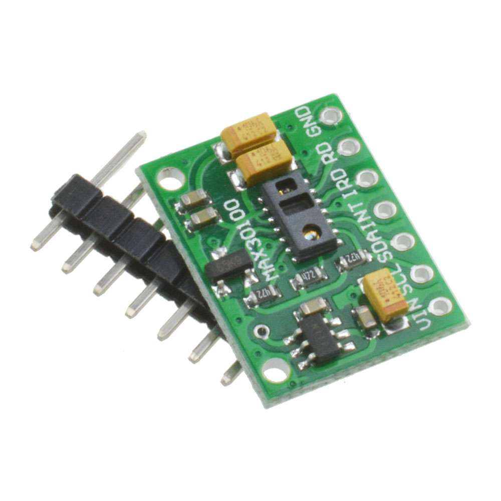
Now if you have the RCWL-0530:
I'm afraid you have more work to do. This cheaper module has some serious design problems.
You see, this module uses this schematic:
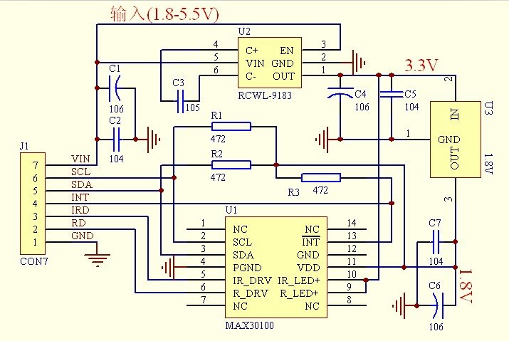
The MAX30100 IC uses 1.8V for VDD and this particular module uses two regulators to achieve this voltage. Nothing wrong with that. However, if you look closely, the SCL and SDA pins are pulled-up via the 4.7k ohm resistors to 1.8V! This means it won't work well with microcontrollers with higher logic levels. The Arduino can detect a minimum HIGH voltage of 2 V!
The solution is to remove the resistors from the board (encircled on the image below) and attach external 4.7k ohms resistors instead.
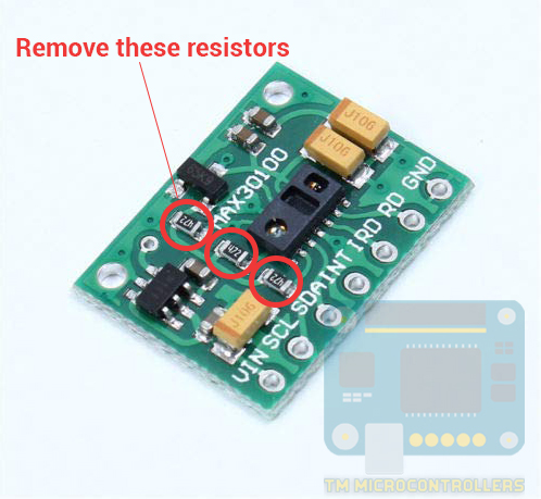
Here's my board with the resistors removed:

After removing the resistors, you can now connect this module to the Arduino UNO using this wiring diagram:
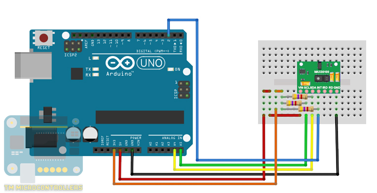
Here, the SCL, SDA and INT pull to 3.3V via the 4.7k ohms resistor. This ensures that the Arduino UNO can detect the HIGH logic level while not oversupplying the MAX30100.
Coding the RCWL-0530 with Arduino
For the sketch, I used this library. The library provides a couple of examples. This is the most basic sketch:
#include <Wire.h>
#include "MAX30100_PulseOximeter.h"

#define REPORTING_PERIOD_MS     1000

// PulseOximeter is the higher level interface to the sensor
// it offers:
//  * beat detection reporting
//  * heart rate calculation
//  * SpO2 (oxidation level) calculation
PulseOximeter pox;

uint32_t tsLastReport = 0;

// Callback (registered below) fired when a pulse is detected
void onBeatDetected()
{
    Serial.println("Beat!");
}

void setup()
{
    Serial.begin(115200);

    Serial.print("Initializing pulse oximeter..");

    // Initialize the PulseOximeter instance
    // Failures are generally due to an improper I2C wiring, missing power supply
    // or wrong target chip
    if (!pox.begin()) {
        Serial.println("FAILED");
        for(;;);
    } else {
        Serial.println("SUCCESS");
    }

    // The default current for the IR LED is 50mA and it could be changed
    //   by uncommenting the following line. Check MAX30100_Registers.h for all the
    //   available options.
    // pox.setIRLedCurrent(MAX30100_LED_CURR_7_6MA);

    // Register a callback for the beat detection
    pox.setOnBeatDetectedCallback(onBeatDetected);
}

void loop()
{
    // Make sure to call update as fast as possible
    pox.update();

    // Asynchronously dump heart rate and oxidation levels to the serial
    // For both, a value of 0 means "invalid"
    if (millis() - tsLastReport > REPORTING_PERIOD_MS) {
        Serial.print("Heart rate:");
        Serial.print(pox.getHeartRate());
        Serial.print("bpm / SpO2:");
        Serial.print(pox.getSpO2());
        Serial.println("%");

        tsLastReport = millis();
    }
}
If you followed the wiring diagram and uploaded this sketch to your Arduino, the red LED on the board should light up and you will see this on the serial monitor:
This means the MAX30100 is running. All you need to do is place your finger on top of the IC (the one with the LED) and your pulse rate should be displayed.
Now if the LED is not turning on, and you are getting the FAILED message on the serial monitor, it might be a power issue. If you look at line 58 of the sketch above:
//pox.setIRLedCurrent(MAX30100_LED_CURR_7_6MA);
This sets the current through the LED. This is originally commented so that the LED current is the default 50 mA. Comment this out to make the current through the LED equal to 7.6 mA! This would solve the power issue.
By the way, here are the other possible values you can use on the setIRLedCurrent() function above:
 MAX30100_LED_CURR_0MA
 MAX30100_LED_CURR_4_4MA
 MAX30100_LED_CURR_7_6MA
 MAX30100_LED_CURR_11MA
 MAX30100_LED_CURR_14_2MA
 MAX30100_LED_CURR_17_4MA
 MAX30100_LED_CURR_20_8MA
 MAX30100_LED_CURR_24MA
 MAX30100_LED_CURR_27_1MA
 MAX30100_LED_CURR_30_6MA
 MAX30100_LED_CURR_33_8MA
 MAX30100_LED_CURR_37MA
 MAX30100_LED_CURR_40_2MA
 MAX30100_LED_CURR_43_6MA
 MAX30100_LED_CURR_46_8MA
 MAX30100_LED_CURR_50MA
Just remember that the higher the current, the brighter the LED and the deeper it reaches your skin.
Sensor Update Speed
The library I am using is very peculiar when it comes to running this line of code:
pox.update();
This line updates the sensor readings and is placed inside the loop(). The author of the library emphasizes that the time between calling this function should be less than 10 ms. As it turns out, you can adjust the sampling frequency of the MAX30100 but in the library, that frequency is set to 100 Hz. Editing the sampling frequency requires the FIR coefficients of the filter used to process the data from the MAX30100.
In short, you can't put a delay of more than 10 ms or do anything that takes that time inside loop() using this code.
This is why for the sketch above, we see this:
if (millis() - tsLastReport > REPORTING_PERIOD_MS) {
   Serial.print("Heart rate:");
   Serial.print(pox.getHeartRate());
   Serial.print("bpm / SpO2:");
   Serial.print(pox.getSpO2());
   Serial.println("%");
   tsLastReport = millis();
}
in reading the sensor values instead of the usual delay() routine. The millis() function continues to run on the background and doesn't block the code execution.
Using an LCD with MAX30100
Because of the timing issues, a problem arises now when using other devices with the MAX30100. Make sure that the pox.update() is executed not less than 100 ms.
In my next example project, I use an I2C LCD with the sensor. Here's the wiring diagram:
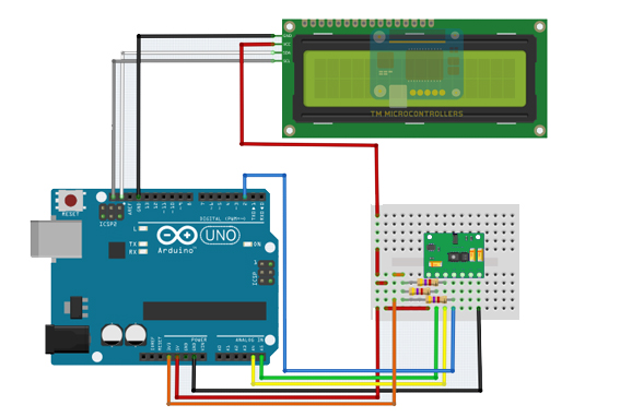
Here's my Arduino Heart Rate Sensor in action:
Here is the sketch for the setup above:
#include <Wire.h>
#include "MAX30100_PulseOximeter.h"
#include <LiquidCrystal_I2C.h>

// Set the LCD address to 0x27 for a 16 chars and 2 line display
LiquidCrystal_I2C lcd(0x27, 16, 2);

#define REPORTING_PERIOD_MS     1000

PulseOximeter pox;

int LED = 13;

uint32_t tsLastReport = 0;

void onBeatDetected()
{
    digitalWrite(LED,!digitalRead(LED));
}
void setup()
{
    lcd.begin();

    // Turn on the blacklight and print a message.
    lcd.backlight();

    lcd.setCursor(0,0);
    lcd.print("Initializing...");
    delay(1000);
    lcd.setCursor(0,1);
    if (!pox.begin()) {
        lcd.print("FAILED");
        while(1);
    } else {
        lcd.print("SUCCESS");
    }

    pox.setIRLedCurrent(MAX30100_LED_CURR_7_6MA);
    pox.setOnBeatDetectedCallback(onBeatDetected);
    delay(1000);
}

void loop()
{
    pox.update();

    if (millis() - tsLastReport > REPORTING_PERIOD_MS) {
        lcd.clear();
        lcd.setCursor(0,0);

        lcd.print("HR: ");
        lcd.print(pox.getHeartRate());
        lcd.print(" bpm");

        lcd.setCursor(0,1);

        lcd.print("SpO2: ");
        lcd.print(pox.getSpO2());
        lcd.print("%");

        tsLastReport = millis();
    }
}
No delay() is inside loop() and display is only updated every second hence the pox.update() is executed as fast as possible.
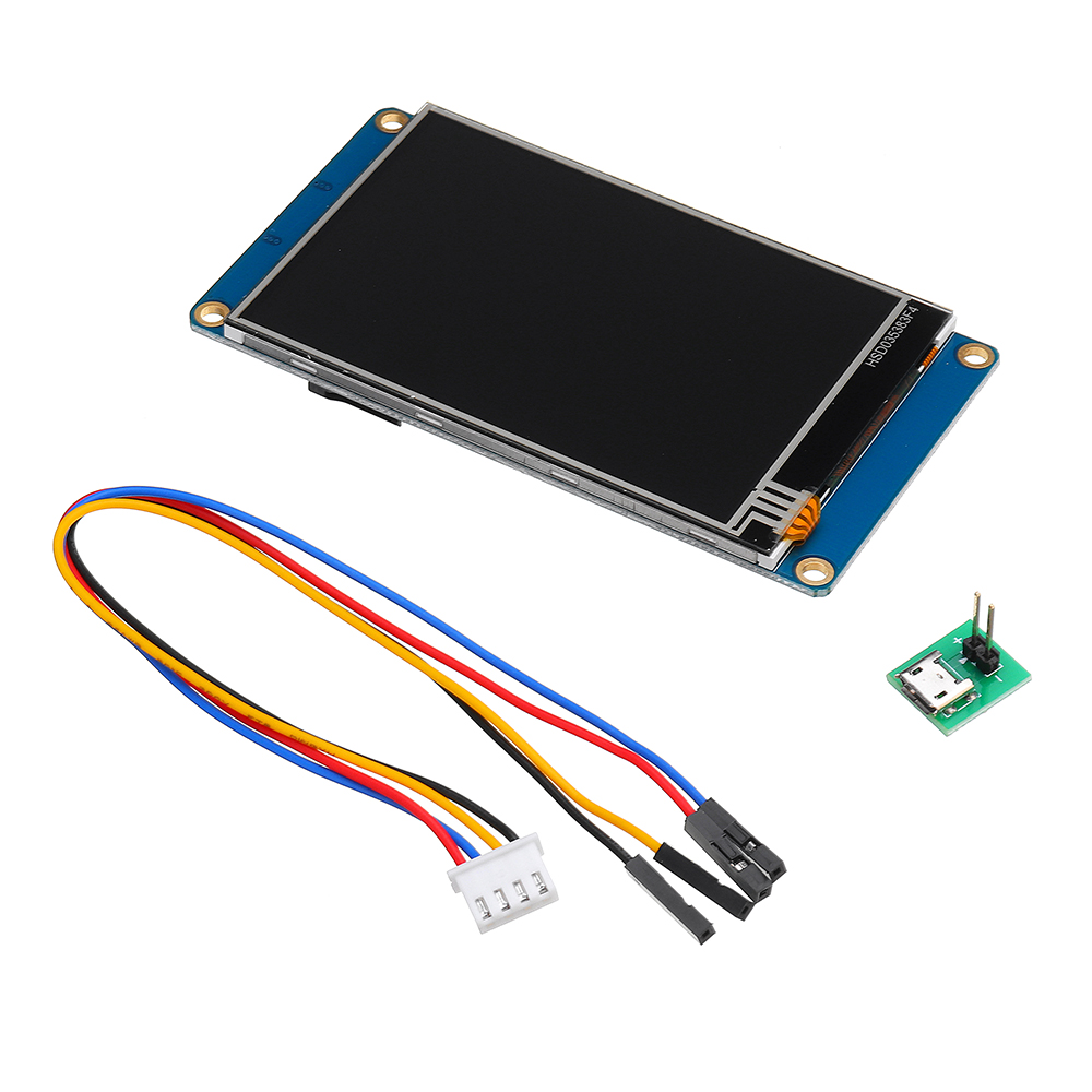
Buy a Touchscreen LCD for your DIY Heart Rate Sensor:


hey, I'm following your instruction, but my max30100 my sensor doesn't work... can you help me?
Hello,
Can you elaborate more? Is there anything displayed on the serial monitor?
when i connect ground arduino to ground max30100 and testing i2c scanner, the sensor can't read the i2c address here the pictures http://bit.ly/Maxpart01 ... and when i did not connect ground arduino and max30100 the sensor can read i2c address... here the pictures : http://bit.ly/MaxPart02
Can SomeOne help me i have the same issue .
My sensors LED is not glowing.
thanks
// pox.setIRLedCurrent(MAX30100_LED_CURR_7_6MA);
Find this line in your code and delete the //. The led should turn on.
If it doesn't, try replacing 7_6 with 11.
Hey, We followed your Instructions and set up the ckt and code but the IRD and RED doesn't glows , what to do?
I have the same issue my sensors LED is doesnot glowing. What to do ?
can i change the analog pin setup for SCL & SDA pin from MAX30100 SENSOR MODULE?
Hi ,
The display time of my data is quite slow for a few minutes to get results . I don't know reason why ? . Can you help me ? ,pls . Thank you.
Thank You so much, your team drive the future.
I did the program in serial monitor its running well.
I want to know the model no of the 0x27 lcd module so that i can bye it and write the programme in the lcd display.
Most likely I2C 1602 Blue Backlight LCD Display Screen Module For Arduino
I was able to modify the breakout board without removing the 4k7 resisters. I did this by breaking the copper track to the 4k7 resisters from the 65K5 and then soldering a link wire to the Vin https://drive.google.com/file/d/12tPpwvfE68EkkASAOVA_JuhV3W7JAx4_/view?usp=sharing
This allowed me to find I2C using I2C scanner and it now operates using either 5v or 3.3v
Unable to find the file which you have shared. Can you provide that file again. It's urgent.
I used the other way to modify this module. I did not remove resistors, but broke through the connection from U3 output to R1,R2,R3 and
connected this line to U2 pin 1 (i.e. to U3 input) and now this module working correctly.
How did You do for broke the connection from U3... please ?, the module is so tiny for doing this . Thank you.
Hello, thank you for your tutorial. Everything worked for me except the last part of wiring LCD with MAX30100.
May I know how much power is connected to the LCD? And hopefully you can share the wiring of the LCD - Arduino.
I am using Arduino UNO. Power supply connected to laptop.
My connections are as below:
LCD:
Vin > 5V
GND > GND
SCL > A5
SDA > A4
MAX30100 (RCWL-0530)
Vin > 3.3V
GND > GND
SCL > SCL (4.7 kOhm parallel pullup)
SDA > SDA (4.7 kOhm parallel pullup)
For the basic MAX30100 sketch, the sensor is able to detect and display values.
However for the MAX30100 and LCD sketch, the LCD displays 0 for sensor values. I tried loading it to print sensor values on serial monitor, but there was no beat detected and sensor values keep updating as 0.
Seems like the MAX30100 could not pick up any values while the LCD and MAX30100 sketch is loaded into the Arduino board.
I really need help on this. Sincerely hoping for your reply. Thank you.
I have the same problem, hope you can see this.
Do you happen to know why i am getting following error?
exit status 1
could not convert 'sensor.MAX30100::begin()' from 'void' to 'bool'
Hello
I want to integrate MAX30100 sensor with DS18B20 sensor
but When I execute it, The DS18B20 sensor works well, but The value of MAX30100 sensor is continuously "0" (both Heart rate and SPO2). and MAX30100 gets hot..
If you can could you help me?
I really need your help
thank you
Hello,
Which MAX30100 board are you using? The green or the purple one?
Hi! I am using the green board and I have the same problem ( It gets pretty hot wittin secondes).
Please is there any way I can get the proteus library files for MAX30100?
Please send me, I want it for may thesis...ylw12jnbr@gmail.com
I'm sorry but I don't have a proteus library for MAX30100.
Great help to start with the max30100.
I found my way to watch with Serial.print + LCD.
Modify the main loop:
void loop()
{
pox.update();
if (millis() - tsLastReport > REPORTING_PERIOD_MS) {
float hr = pox.getHeartRate();
float spo2 = pox.getSpO2();
lcd.clear();
lcd.setCursor(0,0);
lcd.print("HR: ");
lcd.print(hr);
lcd.print(" bpm");
lcd.setCursor(0,1);
lcd.print("SpO2: ");
lcd.print(spo2);
lcd.print("%");
Serial.print("Heart rate:");
Serial.print(hr);
Serial.print("bpm / SpO2:");
Serial.print(spo2);
Serial.println("%");
tsLastReport = millis();
}
}
Thanks for sharing!
can i run it on 9600 baud rate?
can use this code in arduino mega?
Hey It is working. I removed the smd resistors and placed external 4.7k ohm resistor and it worked.If it works red led will start glowing constantly in the max30100 sensor.
Hi! I followed all the steps, however when it displays on the LCD, and I put my finger on the sensor, nothing changes.
Do you think my MAX30100 is defective, there is something wrong with the wirings or did I forget something in the codes?
Thanks a lot for this post! Especially with the RCWL sensor. Kudos for the great job.
Hello thanks for making this post. I try it wit GY-MAX30100 but my code didn't work. The error say that 'pulseoxymeter_t was not declared in this scope'. How could I repair it? I just copy your code. Thank you.
we have removed the 3 inbuilt resistors from the max30100 sensor still in the code it is showing-"Ínitializing pulse oximeter..Failed". what would you suggest?
NIce dude !! You help me,, Thx !
But, i wanna know, how this MAX30100 (greenboard) read its ADC Value ?
I just want to implemented for detecting glucose of blood, any ideas dude ?
Thanks for your post! My green board and I2C LCD work well!
¿This code run to MAX30102?
Hello, i have two problems with the code, the first ist "'Wire' was not declared in this scop"
After inclued the wire.h arduino show me "'pulseoxymeter_t' was not declared in this scope"
Hi,How to improve the results of MAX30100 because it give result non logical and does'n give a stable result
Please help