
Unlike stepper and servo motors, precision control for DC motors is impossible unless a sort of feedback mechanism is employed. If your application requires a consistent motor speed or a stimulant-dependent speed then you certainly need feedback. This tutorial aims to develop a simple motor speed sensor for a more intelligent DC motor control.
The LM393 IR Module
For this tutorial, I will use this inexpensive module:
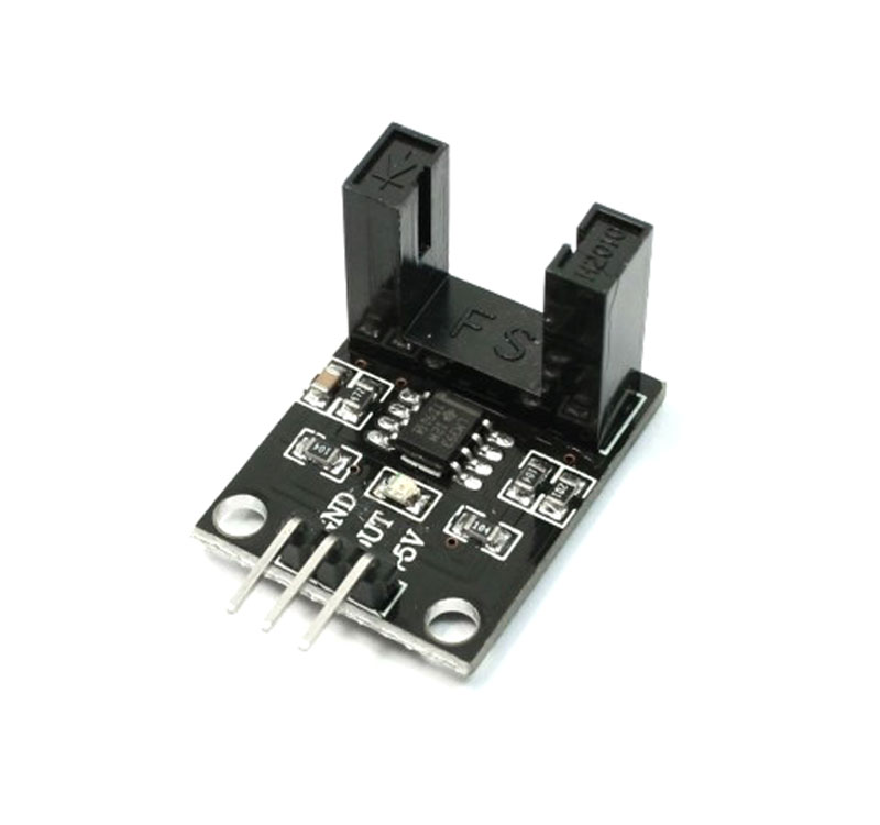
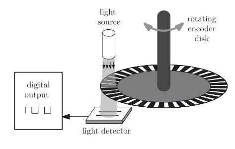
This encoder module has two vertical columns with an IR LED on one column and a phototransistor on the other. Whenever the path between the IR LED and phototransistor is cut, the D0 pin goes high.
Sellers call this module an LM393 speed sensor. The LM393 is in fact a comparator IC and not a sensor, per se. The module schematic is as follows:
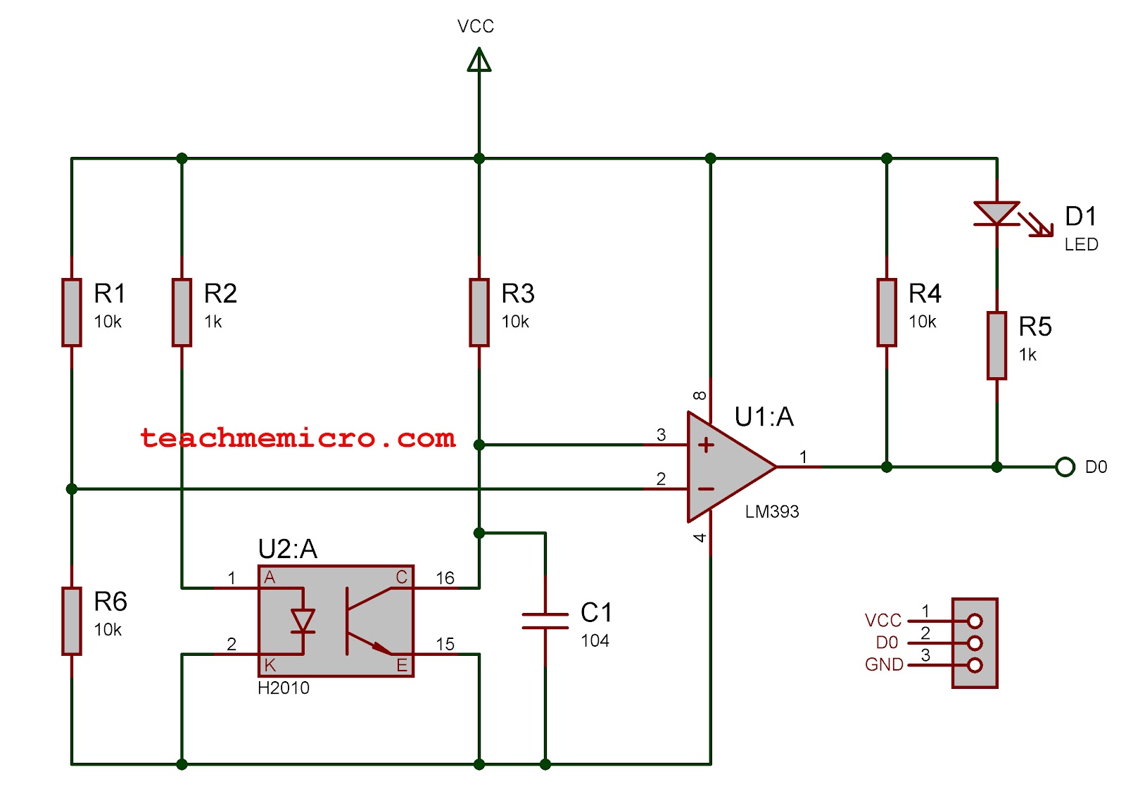
Here we see how simple the circuit for the module is. With no obstruction between the IR LED and phototransistor, the voltage between the positive and negative terminals of the comparator is equal. When the phototransistor is blocked, it will draw a higher voltage, making the positive terminal of the comparator more positive than the negative terminal. Thus, a positive voltage, equal to VCC, will be at the D0 terminal.
Determining Motor Speed
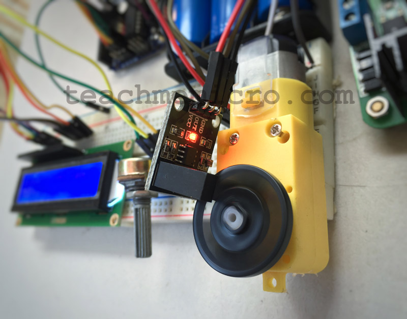
A wheel encoder on the DC motor will help us determine its speed:
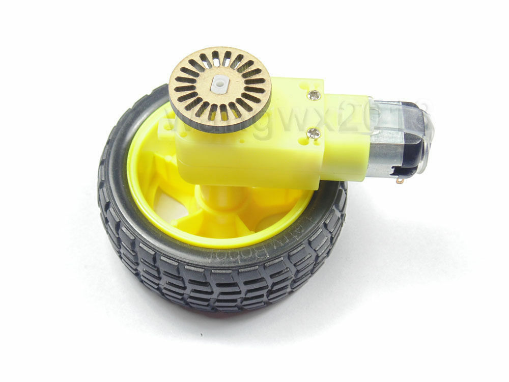
With proper placement, the slots on the encoder will block or pass the IR LED. This will create a train of pulses whose frequency is proportional to the speed of the motor.
The wheel encoder pictured has 20 slots. Therefore, counting 20 pulses means the wheel has traveled one revolution.
If we attach the D0 pin of the module to interrupt 0 of the Arduino, which is digital pin 2, we can count the number of pulses if we have this as the interrupt service routine:
attachInterrupt(0, pulsecount, RISING);

void pulsecount(){
    counter++;
}
The number of revolutions will then be:
Motor speed is normally in revolutions per minute or RPM. Since we have an idea of determining how many revolutions the motor has traveled, all we need is to check the number of revolutions every minute. We can do that through the help of the millis() function inside the loop():
int rpm;
void loop(){
 static uint32_t previousMillis;
 if (millis() - previousMillis >= 1000) {
        rpm = (counter/20)*60;
        counter = 0;
        previousMillis += 1000;
 }
}
Here, we calculate the RPM every 1 second and then reset the pulse counter to 0.
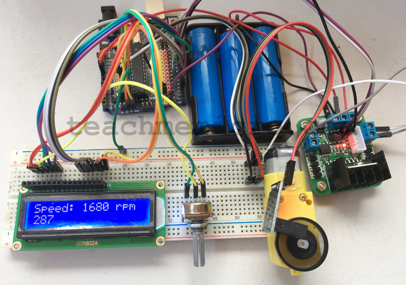
Motor Speed Sensor Project
Using an L298N motor driver, we follow this connection for testing our motor speed sensor:
| Arduino | LCD | L298N Module | LM393 Module |
|---|---|---|---|
| 8 | RS | ||
| 3 | EN | ||
| GND | RW | ||
| 7 | D4 | ||
| 6 | D5 | ||
| 5 | D6 | ||
| 4 | D7 | ||
| 12 | IN1 | ||
| 13 | IN2 | ||
| 9 | ENA | ||
| 2 | D0 | ||
| 5V | 5V | VCC | |
| GND | GND | GND |
I used three 18650 LiPo batteries as a power source. The L298N module has a 5V regulator so this is where the Arduino, LCD, and LM393 module get their power. The DC motor takes on the 11.1 volts from the LiPo batteries.
The speed in RPM is viewable on a 16 x 2 LCD. Here is the full sketch:
#include <LiquidCrystal.h>

int motorIn1 = 12;
int motorIn2 = 13;
int motorEnA = 9;

int encoder = 2;

volatile unsigned int counter;
int rpm;

const int rs = 8, en = 3, d4 = 7, d5 = 6, d6 = 5, d7 = 4;

LiquidCrystal lcd(rs, en, d4, d5, d6, d7);

void setup() {
  pinMode(motorIn1, OUTPUT);
  pinMode(motorIn2, OUTPUT);
  pinMode(motorEnA, OUTPUT);
  pinMode(encoder, INPUT);

  digitalWrite(encoder, HIGH);
  digitalWrite(motorIn1, HIGH);
  digitalWrite(motorIn2, LOW);
  analogWrite(motorEnA, 100);

  attachInterrupt(0,countpulse,RISING);
  lcd.begin(16, 2);
}

void countpulse(){
        counter++;
}

void loop() {
  static uint32_t previousMillis;
  if (millis() - previousMillis >= 1000) {
            rpm = (counter/20)*60;
            counter = 0;
            previousMillis += 1000;
  }

  lcd.setCursor(0,0);
  lcd.print("Speed: ");
  lcd.setCursor(7,0);
  lcd.print(rpm);
  lcd.print(" rps");
  delay(1);
}
This video shows the result of the sketch:
By knowing the speed of the motor, we can now use it as feedback for a PID controller to maintain its speed.


We have purchased a dc motor with a speed of 240 rpm . The link for the motor is attached for your refernce:
https://www.amazon.in/ElectroBot-Wheel-Chassis-Encoder-Arduino/dp/B072XPS46H?tag=googinhydr18418-21.
I have watched your video and you are using the same motor. But in the output video the rpm of the motor is shown in the range of 1200. Please clarify whether both rpm must match or different?. If they are different which is the actual rpm of the motor.