
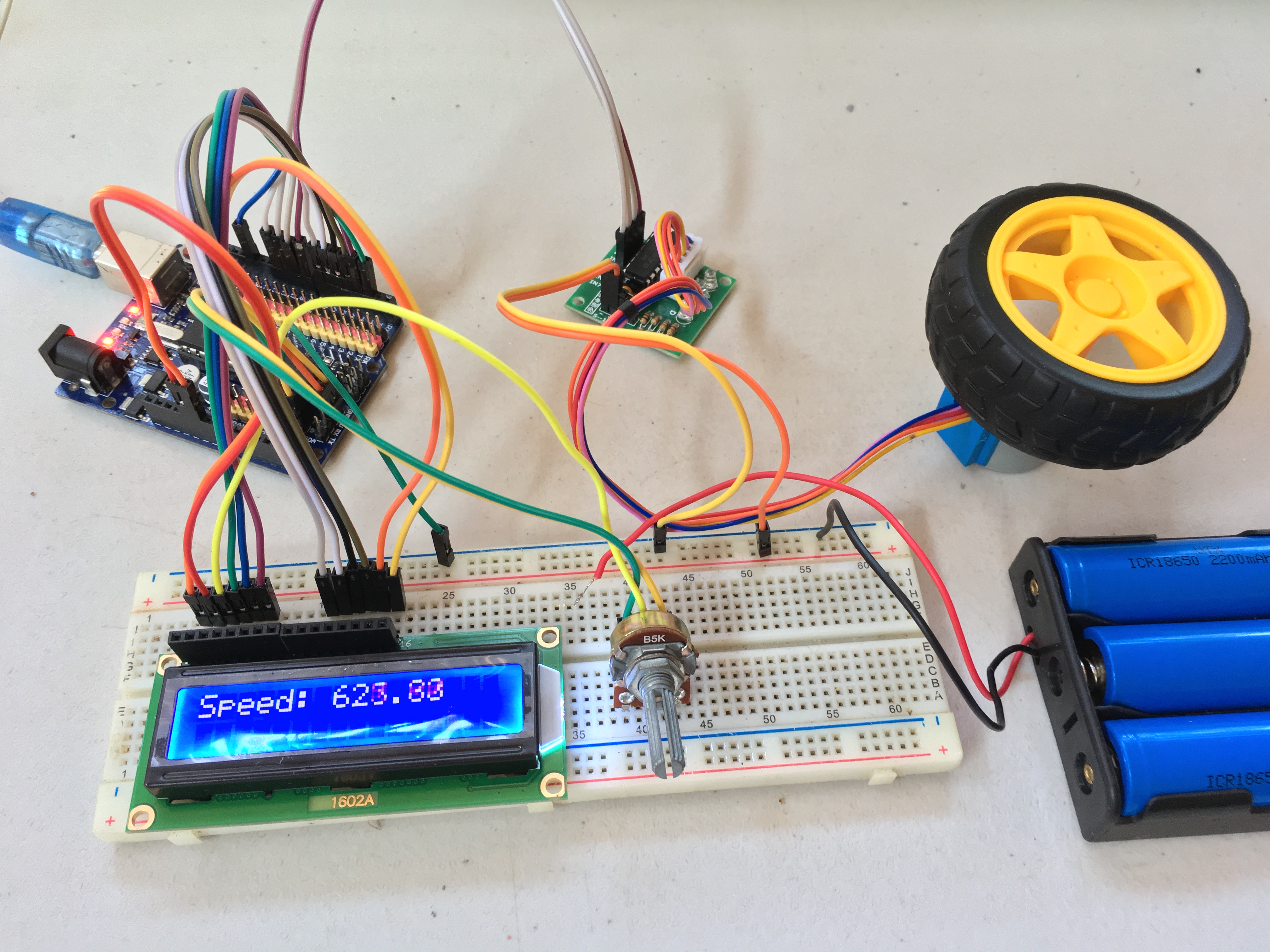
The 28BYJ-48 stepper motor is a cheap and robust stepper motor, suitable for use on robotics and other slow-speed applications. In this tutorial, I will guide you on how to use this stepper motor with Arduino.
Quick Answer: 28BYJ-48 Stepper Motor with Arduino
The 28BYJ-48 stepper motor is a small, inexpensive, geared unipolar stepper motor commonly used with Arduino projects. It is usually paired with a ULN2003 driver board, because the Arduino pins cannot safely drive the motor coils directly.
For a basic Arduino setup, connect the ULN2003 driver inputs to these Arduino pins:
| ULN2003 Pin | Arduino Pin |
|---|---|
| IN1 | 8 |
| IN2 | 9 |
| IN3 | 10 |
| IN4 | 11 |
| VCC | External 5V supply |
| GND | Arduino GND and supply GND |
For simple full-step examples, use 2048 steps per output-shaft revolution. For half-step examples using AccelStepper, use 4096 steps per output-shaft revolution as a practical starting value. If your project needs accurate positioning, calibrate the exact step count because the gearbox ratio can vary slightly between 28BYJ-48 motors.
The easiest way to control the 28BYJ-48 with Arduino is the built-in Stepper library. For smoother motion, acceleration control, and better half-step support, use the AccelStepper library.
28BYJ-48 Stepper Motor Specifications
| Specification | Typical Value |
|---|---|
| Motor type | Unipolar stepper motor |
| Rated voltage | Usually 5V |
| Number of wires | 5 |
| Driver commonly used | ULN2003 driver board |
| Step angle | 5.625° internal step angle |
| Gear ratio | Commonly listed as about 64:1, but actual ratio may vary |
| Full-step output resolution | About 2048 steps/revolution |
| Half-step output resolution | About 4096 steps/revolution |
| Best use cases | Slow positioning, small mechanisms, beginner Arduino projects |
| Not ideal for | High-speed motion, high-torque applications, CNC/3D printer axes |
28BYJ-48 Pinout and Wire Colors
The 28BYJ-48 usually has five wires:
| Wire Color | Function |
|---|---|
| Red | Common wire / motor supply |
| Orange | Coil 1 |
| Yellow | Coil 2 |
| Pink | Coil 3 |
| Blue | Coil 4 |
The red wire is the common supply wire for the motor coils. The other four wires are switched by the ULN2003 driver board to energize the coils in sequence.
How Do Stepper Motors Work?
Before I continue, I find it necessary to review the basics of stepper motors.
The 28BYJ-48 motor is a permanent magnet (PM) type stepper and thus shares similar characteristics with other PM steppers.
A PM stepper motor has a rotating part (rotor) made out of a permanent magnet and a stationary part (stator) of electromagnets. A single motor rotation is divided into steps, hence the name. The number of steps per revolution depends on the number of teeth of the rotor.
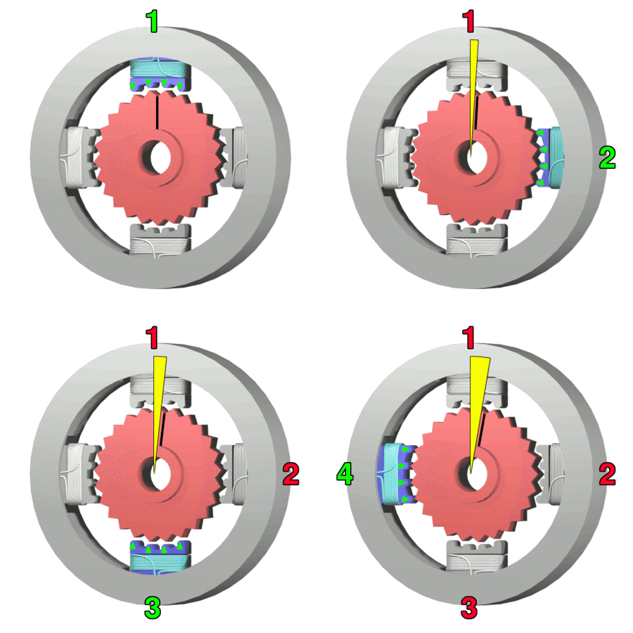
To rotate a stepper motor, the electromagnets must be energized in a circular pattern. The rotor, attracted to an energized electromagnet, follows that rotation. Thus, the speed of the stepper motor depends on the speed of the switching of the electromagnets.
Stepper Motor Polarity
There are bipolar and unipolar stepper motors. In a bipolar stepper motor, the electromagnets are alternately energized:
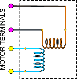
Note that while only two coils (electromagnets) are shown, there could be four coils with the vertical (up and down) and horizontal (left and right) coils each connected in series.
A bipolar stepper motor requires two separate power sources, one for each electromagnet. Because of this, bipolar steppers are not popular with Arduino users. Most high speed stepper motors are bipolar, however.
A unipolar stepper motor follows this diagram:
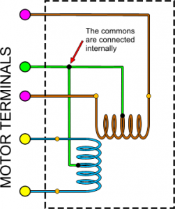
Since the two electromagnets have a common wire, only one power source is necessary for a unipolar stepper motor. The common wire is usually connected to ground.
The 28BYJ-48 is a unipolar stepper motor, with five pins as shown:
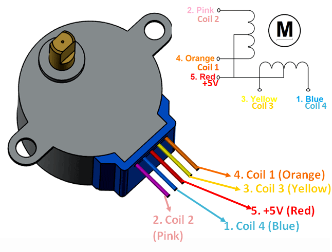
For a unipolar motor, the number of coils is equal to its phase. The 28BYJ-48 has four coils hence, it is a four-phase stepper motor.
More information about this motor is found on its datasheet.
Making a Stepper Motor Rotate
Rotating a stepper motor is often called driving and can be a wave drive, full-step drive, half-step drive or microstep. The last one is complicated and less common so it will not be discussed here.
In a wave drive, one electromagnet or coil is excited at a time:

In a full-step drive, two coils are excited at a time:

Since the full-step drive energizes two coils at a time, it requires more current than a wave step. In exchange of the higher current is higher torque.
A half-step combines a wave and a full-step:

Half-step increases the number of steps per revolution. As you can see in the wave and full-step drives, one revolution takes four steps. In a half-step drive, one revolution takes eight steps. Thus, a half-step drive is recommended for more precise movements.
Note that the animations shown are somewhat simplified. The animations above are simplified. The 28BYJ-48 does not move only 4 or 8 steps per output-shaft revolution. Internally, the motor features a 5.625° step angle, corresponding to 64 steps per internal motor revolution. After the gearbox, the output shaft requires approximately 2048 full steps or 4096 half steps to complete one revolution.
Using a Driver Board for the 28BYJ-48
In this tutorial, we will be using the ULN2003 driver board with the 28BYJ-48.
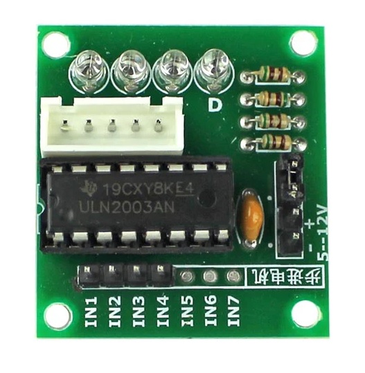
The board has 7 input pins, IN1 to IN7, but only IN1 to IN4 are usable.
It also has pins for power and switching. This allows you to use a separate power supply with a rating of 5 V to 12 V for the motor.
Many ULN2003 driver boards have a motor power input that may be marked for a range of voltages, but the common 28BYJ-48 motor included in Arduino kits is usually the 5V version. For normal use, power the motor from a separate regulated 5V supply. Do not rely on the Arduino 5V pin for motor power.
Programming the Arduino
The Arduino platform contains a built-in stepper library that actually works for the 28BYJ-48. Here is a simple sketch that rotates the stepper in one direction, then to the other direction:
#include <Stepper.h>

const int stepsPerRevolution = 2048;

// initialize the stepper library on pins 8 through 11:
Stepper myStepper(stepsPerRevolution, 8, 9, 10, 11);

void setup() {
  myStepper.setSpeed(10);
  Serial.begin(9600);
}

void loop() {
  Serial.println("clockwise");
  myStepper.step(stepsPerRevolution);
  delay(500);

  Serial.println("counterclockwise");
  myStepper.step(-stepsPerRevolution);
  delay(500);
}
For simple examples, use 2048 steps per revolution in full-step mode or 4096 steps per revolution in half-step mode. Because the 28BYJ-48 uses a small gearbox, the exact value can vary slightly between motors. For precise positioning, calibrate the motor by commanding one revolution and measuring the output shaft.
To use the sketch, connect the stepper motor to the ULN2003 board, then follow this connection to Arduino.
| Controller Board | Arduino |
|---|---|
| IN1 | 8 |
| IN2 | 9 |
| IN3 | 10 |
| IN4 | 11 |
I suggest you use a separate power supply for the motor since it may draw more current than the power pins of the Arduino can provide. I actually did use the Arduino power pins to power the stepper and got one damaged Arduino as a result.
Using a Better Stepper Motor Library
The disadvantage of using the built-in stepper library is that there’s no option to change the stepping mode as it defaults to wave drive only. Also, the built-in library is limited to one stepper motor.
A better library for controlling stepper motors is the AccelStepper library by AirSpayce.
Besides support for half-step driving and multiple motors, the library also offers acceleration and deceleration functions, among other things.
The following sketch rotates the 28BYJ-48 in one direction with a predetermined number of steps:
#include <AccelStepper.h>

// Motor pin definitions
#define motorPin1  8         // IN1 on the ULN2003 driver 1
#define motorPin2  9         // IN2 on the ULN2003 driver 1
#define motorPin3  10         // IN3 on the ULN2003 driver 1
#define motorPin4  11        // IN4 on the ULN2003 driver 1

// Initialize with pin sequence IN1-IN3-IN2-IN4 for using the AccelStepper with 28BYJ-48
AccelStepper stepper(HALF4WIRE , motorPin1, motorPin3, motorPin2, motorPin4);
const long stepsPerRevolution = 4096;
void setup() {
  stepper.setMaxSpeed(800.0);
  stepper.setAcceleration(200.0);
  stepper.moveTo(stepsPerRevolution);
}//--(end setup )---

void loop() {
  stepper.run();

  if (stepper.distanceToGo() == 0) {
    stepper.moveTo(-stepper.currentPosition());
  }
}
The stepper class is initialized in this line:
AccelStepper stepper(HALF4WIRE , motorPin1, motorPin3, motorPin2, motorPin4);
Here, the parameters are the interface (HALF4WIRE) followed by the pin names. The interface parameter accepts the following:
Since the 28BYJ-48 is a four-phase stepper and we want to use half-stepping for precise movements, we used HALF4WIRE as parameter.
As mentioned, one of the strengths of this library is the ability to set the motor acceleration:
stepper.setAcceleration(200.0);
This sets the motor acceleration to 200 steps per second squared.
We can also set the maximum speed of the motor:
stepper.setMaxSpeed(800.0);
Moreover, this line:
stepper.moveTo(stepsPerRevolution);
tells the motor to move one output-shaft revolution, based on the step count we defined earlier.
However, the motor will not move unless this line is placed in the main loop:
stepper.run();
The library is very extensive and contains a number of functions to use. As we can't cover everything in this tutorial, I suggest you check the library's reference page.
An Example Project
I created another sketch where I display the speed and the steps of the stepper motor in a 16x2 LCD:
#include <AccelStepper.h>

// Motor pin definitions
#define motorPin1  8         // IN1 on the ULN2003 driver 1
#define motorPin2  9         // IN2 on the ULN2003 driver 1
#define motorPin3  10         // IN3 on the ULN2003 driver 1
#define motorPin4  11        // IN4 on the ULN2003 driver 1

// Initialize with pin sequence IN1-IN3-IN2-IN4 for using the AccelStepper with 28BYJ-48
AccelStepper stepper(HALF4WIRE, motorPin1, motorPin3, motorPin2, motorPin4);
const long stepsPerRevolution = 4096;

#include <LiquidCrystal.h>

// initialize the library by associating any needed LCD interface pin
// with the arduino pin number it is connected to
const int rs = 2, en = 3, d4 = 7, d5 = 6, d6 = 5, d7 = 4;

LiquidCrystal lcd(rs, en, d4, d5, d6, d7);

void setup() {
  stepper.setMaxSpeed(2000.0);
  stepper.setAcceleration(100.0);
  stepper.setSpeed(200);
  stepper.moveTo(stepsPerRevolution);
  lcd.begin(16, 2);

}//--(end setup )---

void loop() {
  //Change direction when the stepper reaches the target position
  stepper.run();
  if (stepper.distanceToGo() == 0) {
    stepper.moveTo(-stepper.currentPosition());
  }
  lcd.setCursor(0,0);
  lcd.print("Speed:");
  lcd.setCursor(7,0);
  lcd.print(stepper.speed());
  lcd.setCursor(0,1);
  lcd.print("Steps: ");
  lcd.print(stepper.currentPosition());
  lcd.print(" ");
}
The following video shows the result of the above sketch:
Troubleshooting the 28BYJ-48 Stepper Motor
The motor vibrates but does not rotate
This usually means the coil sequence is wrong. If you are using AccelStepper with the ULN2003 board, try the pin order:
AccelStepper stepper(AccelStepper::HALF4WIRE, 8, 10, 9, 11);
This corresponds to the IN1-IN3-IN2-IN4 sequence often needed by the 28BYJ-48 and ULN2003 board.
The Arduino resets when the motor starts
The motor is probably drawing too much current from the Arduino 5V pin. Use a separate regulated 5V power supply for the ULN2003 board and connect the external supply ground to Arduino GND.
The motor turns in the wrong direction
Reverse the step direction in code by using a negative step count or a negative target position.
myStepper.step(-2048);
or:
stepper.moveTo(-4096);
The motor gets hot
Stepper motors can get warm because their coils remain energized while holding a position. However, excessive heat may mean the supply voltage is too high or the motor is stalled.
The motor is too slow
The 28BYJ-48 has a gearbox, which gives it more torque but limits its speed. It is not a good choice for high-RPM applications. For faster and stronger motion, use a larger bipolar stepper motor such as a NEMA 17 with a proper stepper driver.
Frequently Asked Questions
How many steps per revolution does the 28BYJ-48 stepper motor have?
- The common 28BYJ-48 has about 2048 full steps or 4096 half steps per output-shaft revolution. The exact value can vary slightly because the motor uses an internal gearbox.
Can I connect the 28BYJ-48 directly to Arduino pins?
- No. The Arduino pins cannot safely supply the current needed by the motor coils. Use a driver board such as the ULN2003 module.
What power supply should I use for the 28BYJ-48?
- For the common 5V 28BYJ-48, use a separate regulated 5V supply for the motor driver. Connect the external supply ground to the Arduino GND.
Why does my 28BYJ-48 only vibrate?
- The most common cause is an incorrect coil sequence. When using AccelStepper with a ULN2003 board, try the pin order IN1, IN3, IN2, IN4 instead of IN1, IN2, IN3, IN4.
Is the 28BYJ-48 good for high-speed projects?
- No. The 28BYJ-48 is best for slow, low-cost positioning projects. Its gearbox increases torque but limits speed. For higher speed or more torque, use a larger bipolar stepper motor such as a NEMA 17.
Conclusion
The 28BYJ-48 stepper motor is best for low-speed positioning projects where cost, simplicity, and ease of use matter more than speed. It works well with Arduino and the ULN2003 driver board, especially for small mechanisms, gauges, camera sliders, valve controls, and beginner robotics. For faster or stronger motion, a larger bipolar stepper motor, such as a NEMA 17 with a dedicated stepper driver, is a better choice.

28 BYJ-48. Motor has 5 wires. Why is it called 4 wire stepper here
Michael
I never said it’s a four wire stepper. It’s a four-phase stepper with five wires, the fifth wire being VCC.