Building robots with Arduino starts with knowing how to move objects through motors. There are a lot of types of motors used in microcontroller-based systems: DC motors, stepper motors, and servo motors. In this Arduino servo motor article, I will discuss what is a servo motor and how to use it with an Arduino.
Quick answer: To control a servo motor with Arduino, connect the servo signal wire to a digital pin such as D9, connect red to 5V or an external 5–6V supply, connect brown/black to GND, include Servo.h, attach the servo with myservo.attach(9);, then move it using myservo.write(angle);
Introduction to Servo Motors
A servo motor is a special device containing a DC motor, feedback electronics, and a set of gears. It follows the concept of servomechanism.
The operation of the servo motor can be described by the diagram below:
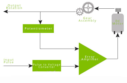
- A servo motor accepts pulses and outputs rotation.
- When the DC motor is at a stop, it means the motor shaft and potentiometer knob are in their equilibrium position. The inputs to the error amplifier are equal and the motor is undriven.
- When a pulse is applied, the two inputs on the error amplifier are no longer equal and thus the amplifier drives the motor. As the motor turns, the gear assembly turns and thus also turns the potentiometer.
- The potentiometer (via voltage divider) generates a voltage equivalent to that of the input pulse that stops the DC motor, indicating equilibrium.
The gear assembly slows down the rotation of the motor to a speed that the potentiometer can catch up. Also, the gears boost the torque output of the servo motor.
Pulse Width and Position
The position of the servo motor arm corresponds with the width of the pulse:

The exact pulse width can vary between servo motor models. If you want to get the exact pulse width for a specific angle, you must test your servo motor.
There is a mechanical stop at the gear assembly to limit the rotation of servo motors to 180 degrees. There are two reasons why servo motors don't rotate for a full circle:
- Originally designed for converting rotational motion to linear motion, servo motors do not need full 360-degree rotation (see crank mechanism).
- The limited possible values for PWM signals need to be mapped to a smaller range (of angles).
There is a way to make a continuous rotation servo which is shown in this tutorial. A continuous rotation servo behaves more like a geared DC motor with built-in control electronics, but it is still controlled using servo-style pulses.
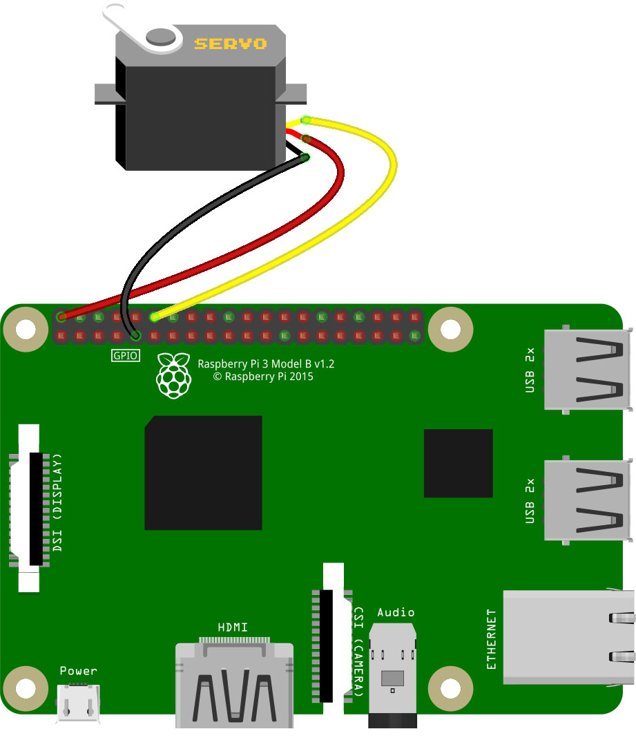
Arduino Servo Motor Wiring Diagram
To begin, wire this circuit:
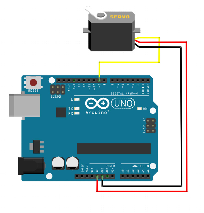
Connect the servo signal wire to a digital I/O pin such as pin 9. It does not have to be one of the Arduino pins marked with ~, because the Servo library generates the required timing pulses for you.
Can Arduino Power a Servo Motor Directly?
For small SG90-style servos, Arduino 5V may work for light testing, but for larger servos such as MG996R/MG995, use a separate 5–6V power source and connect the grounds together.
My MG996R draws 10 mA at idle, 170 mA when operating but without any load connected, and stalls at 1400 mA (!).
Never power a high-torque servo from the Arduino 5V pin under load. The servo can draw far more current than the board can safely provide, causing resets or unstable motion.
Arduino Servo Motor Code
The Arduino Servo library has two easy-to-use examples. This library comes with the IDE so no additional downloads are necessary. We’ll first be using the Sweep example. On the Arduino IDE, go to File > Examples > Servo > Sweep. This sketch will open up:
#include <Servo.h>

Servo myservo; // create servo object to control a servo
// twelve servo objects can be created on most boards

int pos = 0; // variable to store the servo position

void setup()
{
  myservo.attach(9); // attaches the servo on pin 9 to the servo object
}

void loop()
{
  for(pos = 0; pos <= 180; pos += 1) // goes from 0 degrees to 180 degrees
  { // in steps of 1 degree
    myservo.write(pos); // tell servo to go to position in variable 'pos'
    delay(15); // waits 15ms for the servo to reach the position
  }
  for(pos = 180; pos>=0; pos-=1) // goes from 180 degrees to 0 degrees
  {
    myservo.write(pos); // tell servo to go to position in variable 'pos'
    delay(15); // waits 15ms for the servo to reach the position
  }
}
Dissecting the Sketch
Of course, the code starts with
#include <Servo.h>Which simply tells the compiler to include all the Arduino Servo library functions.
Next, you must create a Servo object like this:
Servo myservo;According to the creators of the Servo library, you can create up to 12 servo objects for the UNO and most other boards and up to 48 for the Arduino Mega.
You then need to attach the Servo object to a pin:
myservo.attach(9);To move the servo arm, you use the servo.write() function like so:
for(pos = 0; pos <= 180; pos += 1) // goes from 0 degrees to 180 degrees
{ // in steps of 1 degree
    myservo.write(pos); // tell servo to go to position in variable 'pos'
    delay(15); // waits 15ms for the servo to reach the position
}

for(pos = 180; pos>=0; pos-=1) // goes from 180 degrees to 0 degrees
{
    myservo.write(pos); // tell servo to go to position in variable 'pos'
    delay(15); // waits 15ms for the servo to reach the position
}
The servo.write() function receives the angle in degrees as the argument. In this code snippet, pos is incremented from 0 to 180 inside a for loop and then decremented from 180 to 0 in another for loop.
Controlling a Servo with Microseconds
If you want to control the servo using pulse width instead of degrees, use the writeMicroseconds() function. This is a common example that positions the servo motor arm at the center:
#include <Servo.h>

Servo myservo;

void setup()
{
  myservo.attach(9);
  myservo.writeMicroseconds(1500);  // set servo to mid-point
}

void loop() {}
Here, a 1500 microsecond pulse is generated by the Arduino which is equivalent to 1.5 milliseconds, the pulse width for centering the arm of the servo motor.
Use a Potentiometer to Control a Servo Motor
The other example, the Knob sketch, shows how to control a servo motor with a potentiometer. The voltage from the potentiometer circuit is read through analogRead() and converted to rotation. I used this wiring diagram for this next example:

Knob Sketch:
#include <Servo.h>

Servo myservo;  // create servo object to control a servo

int potpin = 0;  // analog pin used to connect the potentiometer
int val;    // variable to read the value from the analog pin

void setup() {
  myservo.attach(9);  // attaches the servo on pin 9 to the servo object
}

void loop() {
  val = analogRead(potpin);            // reads the value of the potentiometer (value between 0 and 1023)
  val = map(val, 0, 1023, 0, 180);     // scale it to use it with the servo (value between 0 and 180)
  myservo.write(val);                  // sets the servo position according to the scaled value
  delay(15);                           // waits for the servo to get there
}
Similar to the Sweep sketch, the servo motor signal pin is attached to pin 9 of the Arduino UNO. The wiper (middle) arm of the potentiometer is connected to analog pin 0 while the other pins are connected to +5 and GND. With this connection, the potentiometer acts as a voltage divider circuit.
When the wiper arm of the potentiometer is turned, the voltage on the A0 pin changes. Moreover, the minimum value is zero while the maximum value read by the analogRead() function is 1023 according to ADC theory. This range of values is converted to degrees of rotation using the map() function.
Multiple Servo Connections
It's more fun to use more servo motors! However, there are challenges. You cannot use the Arduino's +5V pin to power three or more servo motors because of the current limits of the board. The solution is to have a separate power source for the servo motors. Here is an example diagram:
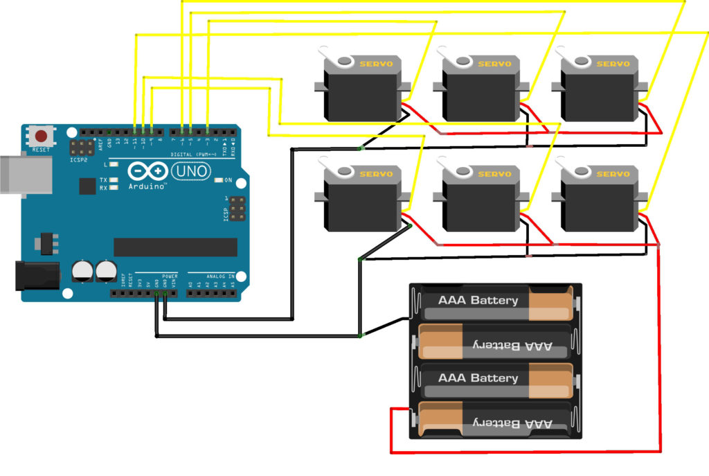
The six servo motors are powered by a 4.8 V battery (rechargeable) pack.
Sketch for Multiple Servo Motors
An example code for testing out multiple servos:
#include <Servo.h>

String readString;

Servo servo1, servo2, servo3, servo4, servo5, servo6;  // create servo objects to control a servo

void setup() {
  Serial.begin(9600);

  servo1.attach(3);
  servo2.attach(5);
  servo3.attach(6);
  servo4.attach(9);
  servo5.attach(10);
  servo6.attach(11);
}

void loop() {

  if (Serial.available())  {
    char c = Serial.read();  //gets one byte from serial buffer
    if (c == ',') {
      if (readString.length() >1) {
        Serial.println(readString); //prints string to serial port out

        int n = readString.toInt();  //convert readString into a number

        // auto select appropriate value, copied from someone elses code.
        if(n >= 500)
        {
          Serial.print("writing Microseconds: ");
          Serial.println(n);
          if(readString.indexOf('1') >=0) servo1.writeMicroseconds(n);
          if(readString.indexOf('2') >=0) servo2.writeMicroseconds(n);
          if(readString.indexOf('3') >=0) servo3.writeMicroseconds(n);
          if(readString.indexOf('4') >=0) servo4.writeMicroseconds(n);
          if(readString.indexOf('5') >=0) servo5.writeMicroseconds(n);
          if(readString.indexOf('6') >=0) servo6.writeMicroseconds(n);
        }
        else
        {
          Serial.print("writing Angle: ");
          Serial.println(n);
          if(readString.indexOf('1') >=0) servo1.write(n);
          if(readString.indexOf('2') >=0) servo2.write(n);
          if(readString.indexOf('3') >=0) servo3.write(n);
          if(readString.indexOf('4') >=0) servo4.write(n);
          if(readString.indexOf('5') >=0) servo5.write(n);
          if(readString.indexOf('6') >=0) servo6.write(n);
        }
         readString=""; //clears variable for new input
      }
    }
    else {
      readString += c; //makes the string readString
    }
  }
}
Upload this sketch above to your UNO board and then open the serial monitor. You can control which servo rotates by typing the servo number on the monitor.
Arduino Servo Troubleshooting
| Problem | Likely cause | Fix |
|---|---|---|
| Servo does not move | Wrong signal pin, missing attach(), no common ground | Check signal pin and connect servo GND to Arduino GND |
| Servo jitters | Weak power supply or noisy wiring | Use external 5–6V supply and add capacitor |
| Arduino resets when servo moves | Servo draws too much current from Arduino 5V | Power servo separately |
| Servo only moves partly | Servo pulse range differs by model | Use attach(pin, min, max) or writeMicroseconds() |
| Servo gets hot or buzzes | Mechanical stop or overloaded horn | Reduce angle range and check the load |
Servo Motor Internals
Here is my MG996R servo motor:
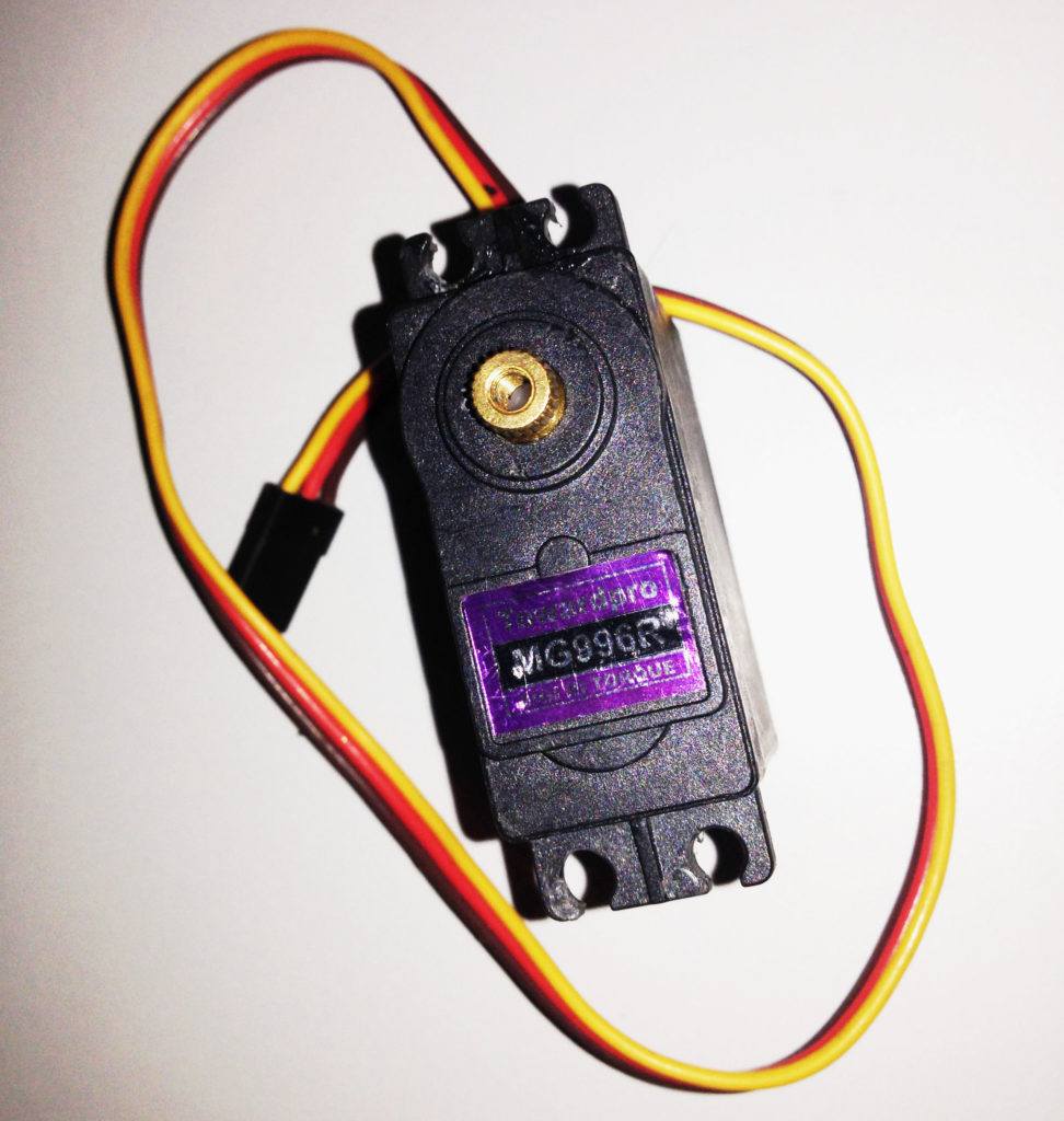
As you can see, there are three wires: red for +5V, black for ground, and yellow for pulse. Other servo motor brands have different colors for their wires but almost all uses red for +5V and black for ground.
This servo motor is capable of producing high torque (rotational force), and thus has metal gears inside:
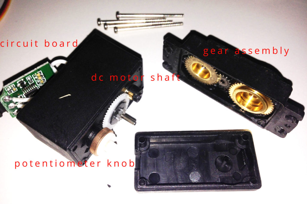
Servo motors that don't produce high torque typically contain plastic gears.
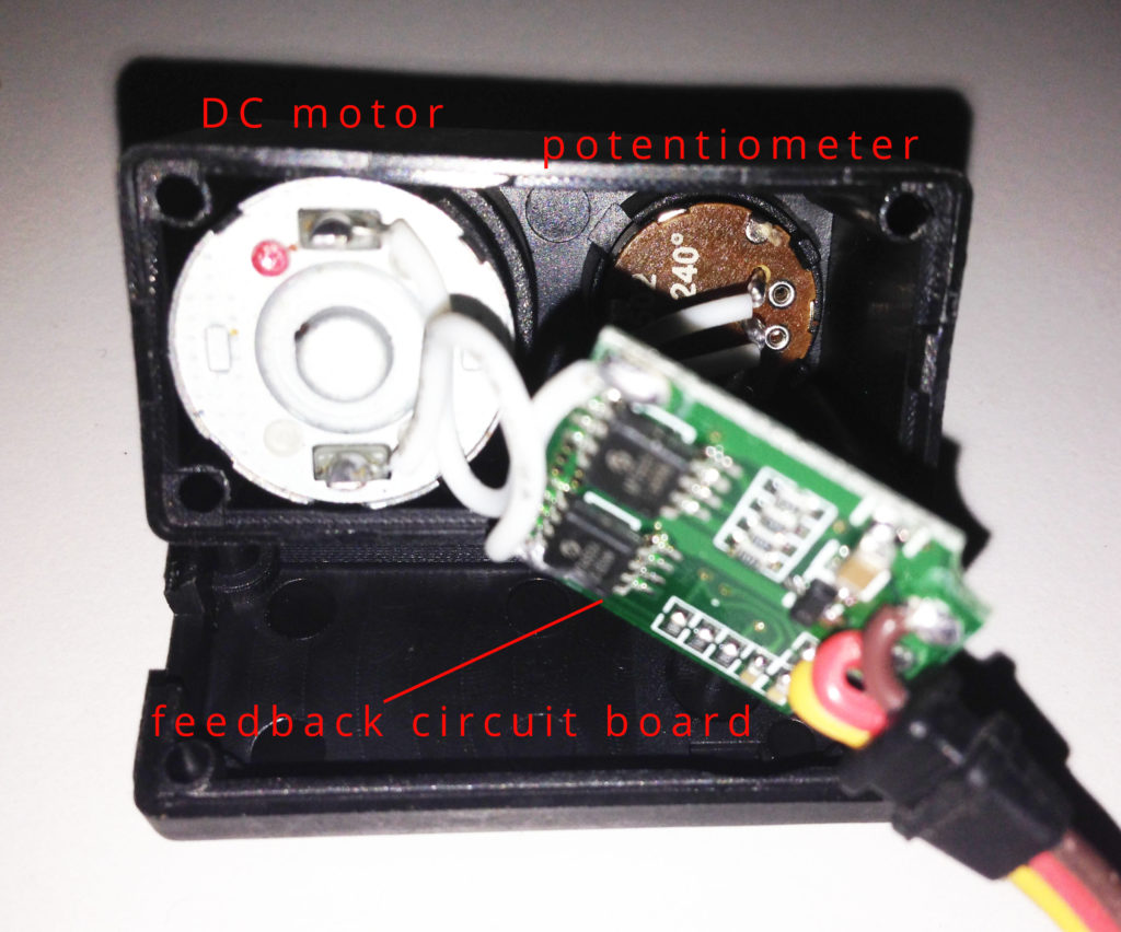
A better look at the circuit board, DC motor and potentiometer:
Arduino Servo FAQ
Can I connect a servo to any Arduino pin?
Yes, when using the Servo library, the signal wire can be connected to a regular digital I/O pin. It does not need to be a ~ PWM pin.
Why does my Arduino reset when the servo moves?
The servo is probably drawing too much current from the Arduino 5V pin. Use a separate 5–6V supply for the servo and connect the servo supply ground to Arduino GND.
What is the difference between write() and writeMicroseconds()?
write() uses an angle from 0 to 180 degrees. writeMicroseconds() sends a pulse width directly, commonly around 1000–2000 µs for many hobby servos, with 1500 µs near center. The Servo library source also lists default pulse constants of 544 µs minimum, 2400 µs maximum, and 1500 µs default pulse width.
Do servo motors use PWM?
They use repeated control pulses, but you should not control a hobby servo with ordinary analogWrite() PWM. Use the Servo library.
How many servos can Arduino Uno control?
The Servo library groups servos by timer, with 12 servos per timer in the library source. Practical limits are usually power supply and timing/resource conflicts, not just the number of signal pins.
Conclusion
Now that you know the basics of servo motors, try recreating my hand-gesture-controlled robotic arm! Here's that project in action:
I hope you found this tutorial useful. Have fun creating with Arduino and servo motors!