
Introduction
The Raspberry Pi Pico is a versatile microcontroller from the Raspberry Pi Foundation. It features the RP2040 microcontroller chip, offering dual-core ARM Cortex-M0+ processors and a variety of I/O pins. Its affordability, GPIO flexibility, and programmability make it an excellent choice for various applications, including motor control projects using devices like the L298N motor driver.
The L298N simplifies the management of DC and stepper motors, allowing for control over speed and direction. This level of motor control is indispensable in scenarios where accuracy and reliability are key factors, such as in robotic vehicles, automated systems, and various electromechanical projects. Integrating the L298N with the Raspberry Pi Pico enhances the capabilities of the microcontroller, providing users with a powerful but cheap solution for motor-driven applications.
This tutorial serves as a guide for makers looking to build projects featuring the Raspberry Pi Pico and the L298N motor driver. My goal is to provide instructions on how to set up, program, and control motors seamlessly. This tutorial aims to help both beginners and experienced hobbyists easily understand Raspberry Pi Pico and L298N motor control for creative DIY projects.
Setting Up Raspberry Pi Pico and Arduino IDE
This tutorial uses Arduino to program the Raspberry Pi Pico. To know how to add the Pico to your Arduino IDE, read this tutorial.
Understanding L298N Motor Driver
Overview of L298N motor driver features

The L298N motor driver boasts essential features for effective motor control. With a dual H-bridge configuration, it supports bidirectional control, enabling precise management of DC motors in both forward and backward directions. This IC drives two motors through two channels, A and B. For example, if a motor is using channel A, its terminals must be connected to pins Out 1 and Out 2. The Enable A pin must be high to turn on the motor. To drive a motor to a direction, say, clockwise, the pin Input 1 must be high while the pin Input 2 must be low. To drive the motor counterclockwise, the pin Input 1 is low while the pin Input 2 is high.
L298N motor controller board
Makers will consider using the L298N breakout board as it is easier for prototyping.
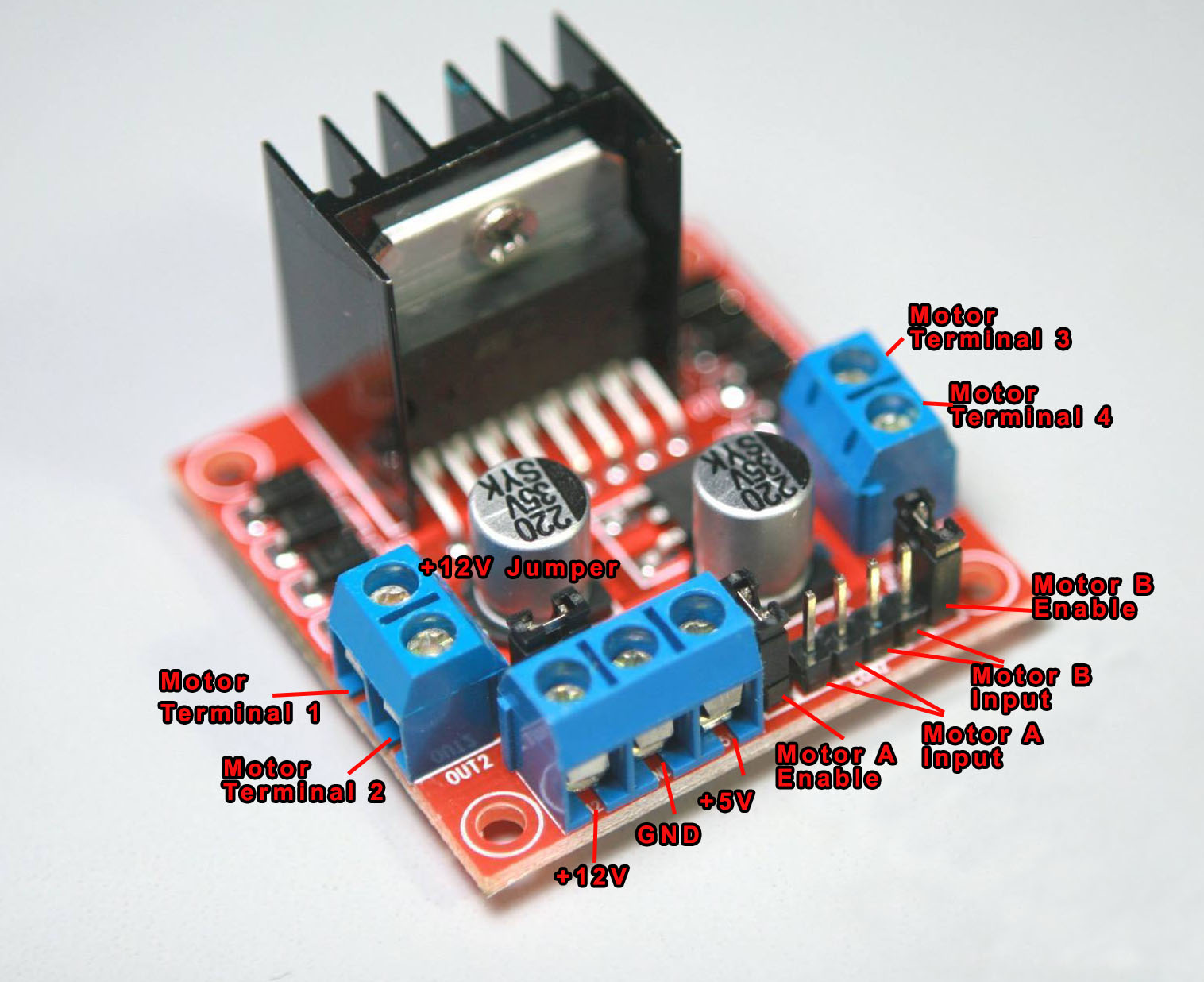
The controller board, shown above, has terminals with labels +12V and +5V. The +12V terminal is where the motor power connects. While it is common to put in +12 VDC to this terminal, it can accept voltages from +7 VDC to +35 VDC. Just remove the jumper behind the +12V terminal if you are planning to power the motors higher than +12V.
When the +12V jumper is attached, the onboard voltage regulator is now usable, and you can source +5V from the +5V terminal. This means the +5V terminal is not for powering the board but for powering a 5V external device.
You have Motor A inputs and Motor B inputs. These connect to the microcontroller. The minimum high voltage is 2.3V, which means the 3.3V logic high from Raspberry Pi Pico is good enough.
The motor terminals connect to Motor Terminals 1, 2, 3, 4. Specifically, motor A connects to terminals 1 and 2 while Motor B connects to terminals 3 and 4.
There are also two other jumpers on the board, as shown. Remove these jumpers if you are using DC motors and keep them for stepper motors. Speed control for Motor A and Motor B is achieved via PWM on these pins.
Connecting L298N to Raspberry Pi Pico and DC Motors
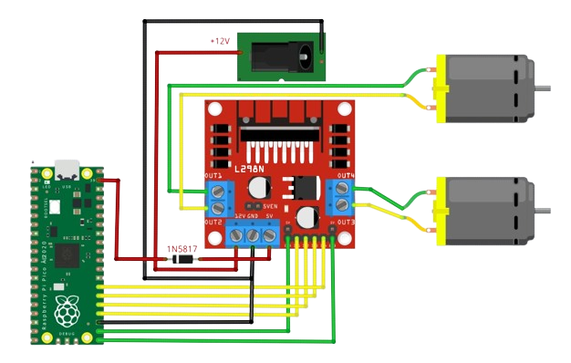
The motor input pins can be connected to any digital I/O pin of the Raspberry Pi Pico. Conversely, the motor-enable pins must be wired to PWM-capable pins. Thankfully for the Pico, almost all of its GPIO pins are PWM-capable.
The Raspberry Pi Pico here gets its power from the L298N board via the 5V terminal. A Schottky diode is added to prevent backpowering. This is a setup suggested in the Raspberry Pi Pico datasheet, section 4.5.
Writing Arduino Code for DC Motor Control
Using the L298N is straightforward. Imagine a robot with two wheels. If you want the robot to move to the left, rotate the right motor forward and rotate the left motor backward.
For the left motor (motor A) to rotate in one direction, apply a high pulse to IN1 and a low pulse to IN2. To reverse the direction, reverse the pulses to IN1 and IN2. The same applies to the right motor (motor B).
Here’s a table that summarizes the pins and corresponding motor direction. This assumes that the upper DC motor is the left motor and the lower one is the right motor.
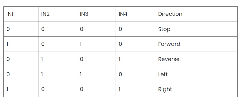
In the code, first, let us define the pins according to the wiring diagram above:
#define EnA 22
#define EnB 21
#define In1 24
#define In2 25
#define In3 26
#define In4 27
Then we initialize all of them as output pins:
void setup()
{
// All motor control pins are outputs
  pinMode(EnA, OUTPUT);
  pinMode(EnB, OUTPUT);
  pinMode(In1, OUTPUT);
  pinMode(In2, OUTPUT);
  pinMode(In3, OUTPUT);
  pinMode(In4, OUTPUT);
}
Next, we create functions corresponding to the actions in the table above: stop, forward, reverse, left, and right.
For stopping the motors, we make all of the motor control pins low, including EnA and EnB.
// Function to stop all motors
void stop ()
{
  digitalWrite(EnA, LOW);
  digitalWrite(EnB, LOW);
  digitalWrite(In1, LOW);
  digitalWrite(In2, LOW);
  digitalWrite(In3, LOW);
  digitalWrite(In4, LOW);
}
To move forward, we enable both motors and make them turn in the same direction. Enabling the motors requires a pulse to EnA/EnB, doable via the analogWrite() command. Here we use a value of 100 out of 255 for our duty cycle. Experiment with which duty cycle value is right for your motors.
// Function to move forward
void forward ()
{
  analogWrite(EnA, 100);
  analogWrite(EnB, 100);
  digitalWrite(In1, HIGH);
  digitalWrite(In2, LOW);
  digitalWrite(In3, HIGH);
  digitalWrite(In4, LOW);
}
To reverse, just logically reverse the function above, keeping the same duty cycle for EnA and EnB.
// Function to move in reverse
void reverse ()
{
  analogWrite(EnA, 100);
  analogWrite(EnB, 100);
  digitalWrite(In1, LOW);
  digitalWrite(In2, HIGH);
  digitalWrite(In3, LOW);
  digitalWrite(In4, HIGH);
}
To move left, rotate the right motor forward and the left motor backward. Moving left logically requires the inverse of moving left.
// Function to move left
void left ()
{
  analogWrite(EnA, 100);
  analogWrite(EnB, 100);
  digitalWrite(In1, LOW);
  digitalWrite(In2, HIGH);
  digitalWrite(In3, HIGH);
  digitalWrite(In4, LOW);
}

// Function to move right
void right ()
{
  analogWrite(EnA, 100);
  analogWrite(EnB, 100);
  digitalWrite(In1, HIGH);
  digitalWrite(In2, LOW);
  digitalWrite(In3, LOW);
  digitalWrite(In4, HIGH);
}
Now we have all five functions to control our motors! Simply call them inside the loop() method.
Example Code
You can find an example code in this repository where you can control the direction of the motors via a serial monitor. For example, if you type “forward”, the motors will move forward, and so on.
Connecting L298N to Raspberry Pi Pico and DC Motors
The L298N can also control stepper motors, specifically bipolar stepper motors. This time, the enable-pin jumpers must be on. The four pins from the stepper motor then connect to the motor output pins of the L298N module. Here is a wiring diagram featuring the Raspberry Pi Pico as the microcontroller:
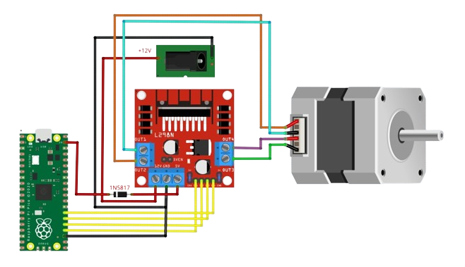
To rotate the stepper motor, the motor output pins must provide power in a specific sequence. The four pins of the stepper motor are the end of the coils in this diagram:
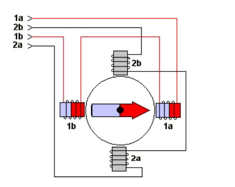
When powering the coils in sequence, the permanent magnet rotor rotates according to that sequence. For simplicity, we will implement what is called a half-step drive:
Writing Arduino Code for Stepper Motor Control
The Arduino platform contains a built-in stepper library called Stepper. To use, include <Stepper.h>
#include <Stepper.h>

#define In1 24
#define In2 25
#define In3 26
#define In4 27

const int stepsPerRevolution = 64;

// initialize the stepper library on pins 8 through 11:
Stepper myStepper(stepsPerRevolution, In1, In2, In3, In4);
Set the stepper motor speed inside setup()
void setup() {
//Set the speed at 60 rpm:
  myStepper.setSpeed(60);
// initialize the serial port:
  Serial.begin(9600);
}
To move the stepper motor, call the step() function with an argument equal to the steps per revolution.
myStepper.step(stepsPerRevolution);
Here is a simple sketch that rotates the stepper in one direction and then in the other direction.
#include <Stepper.h>

const int stepsPerRevolution = 64; // change this to fit the number of steps per revolution
// for your motor

// initialize the stepper library on pins 8 through 11:
Stepper myStepper(stepsPerRevolution, 8, 9, 10, 11);

void setup() {
// set the speed at 60 rpm:
  myStepper.setSpeed(60);
// initialize the serial port:
  Serial.begin(9600);
}

void loop() {
// step one revolution in one direction:
  Serial.println("clockwise");
  myStepper.step(stepsPerRevolution);
  delay(500);

// step one revolution in the other direction:
  Serial.println("counterclockwise");
  myStepper.step(-stepsPerRevolution);
  delay(500);
}
The disadvantage of using the built-in stepper library is that there’s no option to change the stepping mode as it defaults to wave drive only. When the stepper motor is moving, it blocks other Arduino functions. Also, the built-in library is limited to one stepper motor.
A better library for controlling stepper motors is the AccelStepper library by AirSpayce. Besides support for half-step driving and multiple motors, the library also offers acceleration and deceleration functions, among other things.
I hope that this tutorial, in some way, helps makers like you and me. For any questions, reactions, or concerns, feel free to drop comments below. You can also follow our Facebook, TikTok, and Instagram accounts. As always, happy building!


