
Introduction
Beginner tutorials on the web often use the HC-SR04 ultrasonic sensor. Why? Because it’s easy to use and requires a few short lines of code. So when I tried it with the Raspberry Pi Pico, I expected it to work immediately. Until it didn’t.
Fortunately, I made it to work, thanks to a few days of scouring the internet. I made this tutorial hoping that you will not spend the same time as me.
The code in this tutorial uses the Raspberry Pi Pico Arduino core by Earle F. Philhower. Head over to this tutorial on how to set it up.
How the HC-SR04 Ultrasonic Sensor Works
I always assume every one of my readers is a beginner. So I have to give every detail including how the sensor works. If you already know this, kindly skip to the next section.
The ultrasonic sensor works by knowing the time between sending a sound and having that sound reflected to its source. The distance then between the sound source and the reflector is half that time multiplied by the speed of sound. The sound is above the hearing range of humans hence it’s called "ultra" sonic.
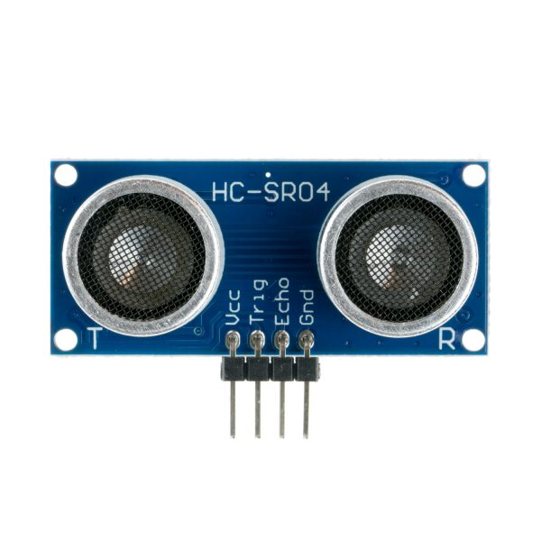
The HC-SR04 has four pins: VCC, GND, TRIG, and ECHO. VCC and GND are where you will apply the 5V DC source. TRIG, short for trigger is where you enable the sensor to send an ultrasonic signal. ECHO is where a pulse can be measured that is proportional to the distance between the sensor and the obstacle.
The TRIG pin requires a 10 µs pulse for it to start emitting 8 cycles of signal. After the ultrasonic signal is sent, the ECHO pin goes from LOW to HIGH and stays HIGH. The ECHO pin only goes LOW when the ultrasonic signal is reflected to the sensor (hence, the word “echo”). Reflection only happens when the signal is obstructed, hence the distance traveled by the signal from the sensor and back is known if the time between the the ECHO pin going HIGH then going LOW is known. If t is that time, then the distance from the sensor to the obstacle is:
distance = speed of sound * t / 2;
The HC-SR04 can measure the distance from an obstruction if it’s within 2 centimeters to 4 meters (unverified, probably less) and 15 degrees of the viewing angle.
Some Tips
If in case your ultrasonic sensor is not working as intended, take note of the following scenarios:
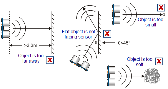
An upgrade of the HC-SR04 is the 5-pin HY-SRF05. When the fifth pin is grounded, you can use the TRIG pin as the ECHO pin. This reduces the number of pins used. The HY-SRF05 also claims to have a longer range than the HC-SR04. I will verify this as soon as I get my hands on one.
Wiring Diagram
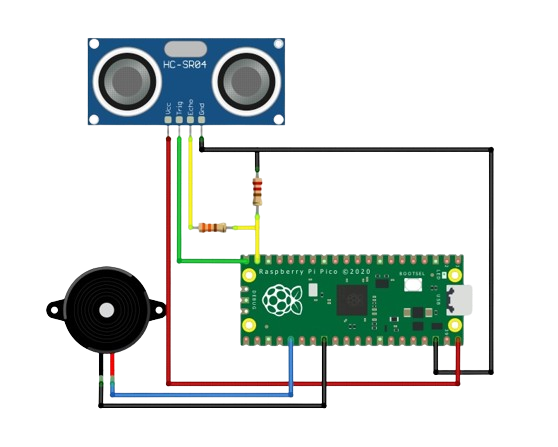
The TRIG and ECHO pin may be connected to any GPIO pin of the Raspberry Pi Pico. I choose GPIO15 for the TRIG and GPIO14 for the ECHO. The HC-SR04 needs 5V to turn on so we use the VBUS pin. Note that the VBUS pin gets the 5V DC power from the USB connection of the Pico. We add a voltage divider between the ECHO and GPIO14 since the HC-SR04 sends a 5V signal and the Pico pin is only 3.3V tolerant. An optional (3V) buzzer can be connected to GPIO19. This buzzer’s sound changes with the distance of the obstacle from the sensor.
Code Explanation
Sending Pulse
The HC-SR04 is a common sensor for interfacing with an Arduino. Using the code that is easily found in the internet didn't work initially. I found out that a voltage divider is needed because the HC-SR04 sends 5V pulses from the echo pin to the 3.3V GPIO pins of the Pico.
First, we send a 10 µs pulse to the trigger pin. This will make HC-SR04 send out 8 pulses of ultrasonic signal.
  digitalWrite(trig_pin, LOW);
  delayMicroseconds(2);
  digitalWrite(trig_pin, HIGH);
  delayMicroseconds(TRIG_PULSE_DURATION_US);
  digitalWrite(trig_pin, LOW);
Measuring Distance
After sending the pulse, the echo pin will now be in the high state. We note this as the start of the travel of the ultrasonic signal. We use the pulseIn() function to measure the time between HIGH and LOW state of the echo pin
echo_time = pulseIn(echo_pin, HIGH);
The distance traveled by the signal is then:
distance = speed * echo_time
Speed here would be the speed of sound and time is the difference between the time the echo pin going high and then the time it went low. Also, we need to convert the speed of sound to centimeters per microsecond since the measured time was in microseconds. Also, since the HC-SR04’s range is from 2 to 4 centimeters only, it makes sense to use centimeters for the distance.
distance = 331.3 * echo_time * 0.0001 (in cm)
This distance is the distance traveled by the signal from the sensor, to the obstacle and back to the sensor. We want to know only the distance between the sensor and the obstacle. So, we divide the total distance in half.
distance = (331.3 * echo_time * 0.0001) / 2 (in cm)
Btw, an optional buzzer can be connected to GPIO19. The buzzer’s sound will change with the distance of the obstacle from the front of the sensor. That part is inside the loop():
analogWrite(buzz_pin, distance_cm * 10000.00);
Effect of Temperature
The speed of sound is not constant in every environment. Its speed is different in the desert compared to a freezing tundra, for example.
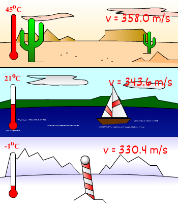
The formula for the speed of sound considering temperature is:
Thus, in the code, I used the internal temperature sensor of the Raspberry Pi Pico to compensate for temperature changes:
  float comp_sound_speed = SOUND_SPEED + 0.606 * analogReadTemp();
  float distance_cm = 0.0001 * ((receiveTime - delayTime) * comp_sound_speed) / 2;
Here’s the link to download the full sketch/code.


