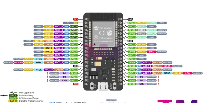
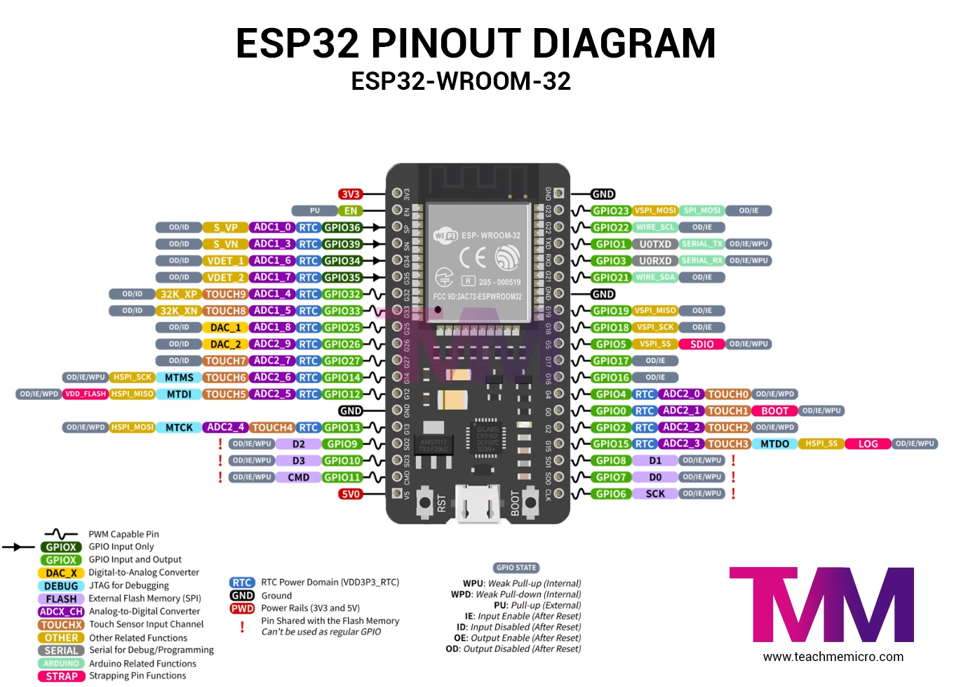
This guide shows the GPIO pins, ADC channels, power pins, boot pins, communication pins, and safe-to-use pins on the ESP32-WROOM-32 development board. Use the diagram and tables below to choose the right pins for sensors, I2C, SPI, UART, PWM, touch input, and analog readings.
The guide shows the 30-pin and 38-pin ESP32 development boards based on the ESP32-WROOM-32 module.
Quick Answer: Best ESP32 GPIO Pins to Use
For most beginner ESP32 projects, the safest GPIO pins to use are GPIO 13, 14, 16, 17, 18, 19, 21, 22, 23, 25, 26, 27, 32, and 33.
Use GPIO 34, 35, 36, and 39 only as inputs. Avoid GPIO 6 to GPIO 11 because they are connected to the ESP32’s internal SPI flash. Be careful with GPIO 0, 2, 5, 12, and 15 because they affect the ESP32 boot mode.
| Pin group | GPIO pins | Recommendation |
|---|---|---|
| Safe general GPIO | 13, 14, 16, 17, 18, 19, 21, 22, 23, 25, 26, 27, 32, 33 | Good for most projects |
| Input only | 34, 35, 36, 39 | Inputs only; no output |
| Avoid | 6, 7, 8, 9, 10, 11 | Connected to SPI flash |
| Boot/strapping pins | 0, 2, 5, 12, 15 | Use with caution |
| Default I2C | 21, 22 | SDA, SCL |
| Common VSPI | 23, 19, 18, 5 | MOSI, MISO, SCK, CS |
| UART0 | 1, 3 | Used for serial/upload |
ESP32 Pinout Description
The ESP32 pins are categorized into digital pins, analog pins, and power pins. Refer to the table below for details on pins with secondary functions. Moreover, these secondary pins often serve communication purposes, such as I2C and SPI or as ADC channels.
| Pin Name | Description | Pin Name | Description |
|---|---|---|---|
| 3V3 | 3.3 V power supply | GND | Ground |
| EN | CHIP_PU, Reset | IO23 | GPIO23 |
| VP | GPIO36, ADC1_CH0, S_VP | IO22 | GPIO22 |
| VN | GPIO39, ADC1_CH3, S_VN | TX | GPIO1, U0TXD |
| IO34 | GPIO34, ADC1_CH6, VDET_1 | RX | GPIO3, U0RXD |
| IO35 | GPIO35, ADC1_CH7, VDET_2 | IO21 | GPIO21 |
| IO32 | GPIO32, ADC1_CH4, TOUCH_CH9, XTAL_32K_P | GND | Ground |
| IO33 | GPIO33, ADC1_CH5, TOUCH_CH8, XTAL_32K_N | IO19 | GPIO19 |
| IO25 | GPIO25, ADC1_CH8, DAC_1 | IO18 | GPIO18 |
| IO26 | GPIO26, ADC2_CH9, DAC_2 | IO5 | GPIO5 |
| IO27 | GPIO27, ADC2_CH7, TOUCH_CH7 | IO17 | GPIO17 3 |
| IO14 | GPIO14, ADC2_CH6, TOUCH_CH6, MTMS | IO16 | GPIO16 3 |
| IO12 | GPIO12, ADC2_CH5, TOUCH_CH5, MTDI | IO4 | GPIO4, ADC2_CH0, TOUCH_CH0 |
| GND | Ground | IO0 | GPIO0, ADC2_CH1, TOUCH_CH1, Boot |
| IO13 | GPIO13, ADC2_CH4, TOUCH_CH4, MTCK | IO2 | GPIO2, ADC2_CH2, TOUCH_CH2 |
| D2 | GPIO9, D2 2 | IO15 | GPIO15, ADC2_CH3, TOUCH_CH3, MTDO |
| D3 | GPIO10, D3 2 | D1 | GPIO8, D1 2 |
| CMD | GPIO11, CMD 2 | D0 | GPIO7, D0 2 |
| 5V | 5 V power supply | CLK | GPIO6, CLK 2 |
Safe ESP32 General-Purpose GPIO Pins
The safest ESP32 pins for general digital input and output are:
- GPIO13
- GPIO14
- GPIO16
- GPIO17
- GPIO18
- GPIO19
- GPIO21
- GPIO22
- GPIO23
- GPIO25
- GPIO26
- GPIO27
- GPIO32
- GPIO33
These pins are usually safe for LEDs, relays, buttons, sensors, and general digital control. Some of them are also commonly used for I2C, SPI, UART, PWM, and other peripheral functions.
ESP32 Input-Only Pins
GPIO34, GPIO35, GPIO36, and GPIO39 are input-only pins. They can read digital or analog signals, but they cannot be used as output pins.
Use these pins for sensors, switches, analog inputs, and other input signals. Also note that GPIO34 to GPIO39 do not have internal pull-up or pull-down resistors, so you may need external resistors when using them with buttons or open-drain/open-collector signals.
ESP32 Pins to Avoid
Avoid using GPIO6, GPIO7, GPIO8, GPIO9, GPIO10, and GPIO11. These pins are connected to the ESP32 module’s internal SPI flash memory and are not available as normal GPIO pins on most ESP32-WROOM-32 boards.
Using these pins can cause boot problems, crashes, or unstable behavior.
ESP32 Boot, Strapping, and Flashing Mode Pins
Some ESP32 pins are read during startup to decide how the chip boots. These are called strapping pins. GPIO0 is especially important because pulling it LOW during reset puts the ESP32 into flashing mode for uploading firmware.
Be careful when using:
- GPIO0
- GPIO2
- GPIO5
- GPIO12
- GPIO15
If external circuits pull these pins to the wrong level during reset, the ESP32 may fail to boot or may enter programming mode unexpectedly.
ESP32 Analog to Digital Converter Pins and Wi-Fi Warning
The ESP32 has ADC1 and ADC2 pins for analog input. If your project uses Wi-Fi, it is better to use ADC1 pins for analog readings.
ADC1 pins include:
- GPIO32
- GPIO33
- GPIO34
- GPIO35
- GPIO36
- GPIO39
ADC2 pins can conflict with Wi-Fi because ADC2 is used by the Wi-Fi driver. If Wi-Fi is active, analogRead() on ADC2 pins may fail or behave unreliably. For Wi-Fi projects, use ADC1 pins whenever possible.
ESP32 DAC Pins
The ESP32 has two DAC output pins:
- GPIO25: DAC1
- GPIO26: DAC2
These pins can output analog-like voltage levels and are useful for simple audio, waveform generation, and analog control signals.
ESP32 Touch Pins
The ESP32 has capacitive touch pins that can detect touch without a mechanical button. Common touch-capable pins include GPIO4, GPIO12, GPIO13, GPIO14, GPIO15, GPIO27, GPIO32, and GPIO33.
These pins are useful for touch buttons, wake-up inputs, and simple human-interface projects.
ESP32 Deep Sleep Wake-Up Pins
The ESP32 can wake from deep sleep using selected GPIO pins. The input-only RTC GPIO pins, such as GPIO34, GPIO35, GPIO36, and GPIO39, are often useful for wake-up inputs because they are not needed for output control.
For deep sleep projects, avoid connecting wake-up circuits to bootstrapping pins unless you are sure the external circuit will not affect the ESP32 startup state.
ESP32 I2C Pins
The common default I2C pins on ESP32 are:
- GPIO21: SDA
- GPIO22: SCL
These pins are commonly used for sensors, LCDs, OLED displays, RTC modules, and other I2C devices.
ESP32 SPI Pins
The common VSPI pins on ESP32 are:
- GPIO23: MOSI
- GPIO19: MISO
- GPIO18: SCK
- GPIO5: CS
You can also use other pins through software configuration, but these are the common default SPI pins used in many ESP32 examples.
ESP32 UART Pins
The default serial pins are:
- GPIO1: TX0
- GPIO3: RX0
These are connected to the USB-to-serial interface on many ESP32 development boards, so avoid using them for other devices if you need Serial Monitor or code uploading.
ESP32 Power Pins
The ESP32 development board usually has the following power pins:
- 3V3: regulated 3.3 V output
- 5V or VIN: 5 V input/output depending on the board
- GND: ground
- EN: enable/reset pin
The ESP32 GPIO pins are not 5 V tolerant. Use 3.3 V logic levels when connecting sensors and modules.
ESP32-WROOM-32 Module vs ESP32 Development Board
The ESP32-WROOM-32 is the metal-shielded module that contains the ESP32 chip, flash memory, crystal, and antenna circuit. The development board adds extra parts such as the USB-to-serial converter, voltage regulator, reset button, boot button, and pin headers.
Because of this, the ESP32-WROOM-32 module pinout and the ESP32 development board pinout are related, but they are not always exactly the same.
Common ESP32 Pinout Mistakes
Here are common mistakes when choosing ESP32 pins:
- Using GPIO6 to GPIO11 as normal GPIO pins
- Using GPIO34 to GPIO39 as output pins
- Connecting 5 V signals directly to ESP32 GPIO pins
- Using ADC2 pins while Wi-Fi is active
- Pulling boot pins to the wrong level during reset
- Using GPIO1 and GPIO3 while also relying on Serial Monitor
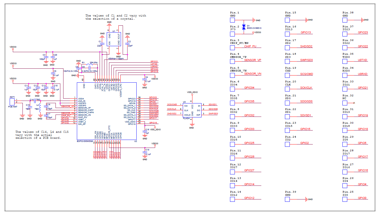
ESP32 WROOM-32 Schematic Diagram
The schematic diagram below is a useful reference together with the pinout as you make your project.
(Click to view larger image)
Do you want some ESP32 project ideas? Check out the following tutorials:
- Sensor Display on ESP32 Web Server
- ESP32 Turbidity Sensor
- ESP32 Magnetometer using HMC5883L
- ESP32 MAX7219 WiFi Message Board
- Using Restful APIs with ESP32
- ESP32 Pressure Sensor
... and many more! See our ESP32 Tutorial archive.
ESP32 Pinout FAQ
What is the best ESP32 pin to use for output?
GPIO13, GPIO14, GPIO16, GPIO17, GPIO18, GPIO19, GPIO21, GPIO22, GPIO23, GPIO25, GPIO26, GPIO27, GPIO32, and GPIO33 are good choices for general digital output.
Which ESP32 pins should I avoid?
Avoid GPIO6 to GPIO11 because they are connected to SPI flash. Also be careful with GPIO0, GPIO2, GPIO5, GPIO12, and GPIO15 because they affect boot mode.
Which ESP32 pins are input only?
GPIO34, GPIO35, GPIO36, and GPIO39 are input-only pins.
What are the default I2C pins on ESP32?
The common default I2C pins are GPIO21 for SDA and GPIO22 for SCL.
What are the default SPI pins on ESP32?
The common VSPI pins are GPIO23 for MOSI, GPIO19 for MISO, GPIO18 for SCK, and GPIO5 for CS.
Is ESP32-WROOM-32 the same as ESP32 WROOM 32?
Yes. ESP32-WROOM-32, ESP32 WROOM 32, ESP-WROOM-32, ESP32WROOM32, and ESP32 WROOM-32 are common ways people refer to the same module family.
Are ESP32 GPIO pins 5V tolerant?
No. ESP32 GPIO pins use 3.3 V logic and should not be connected directly to 5 V signals. Use a voltage divider or level shifter when connecting 5 V modules.