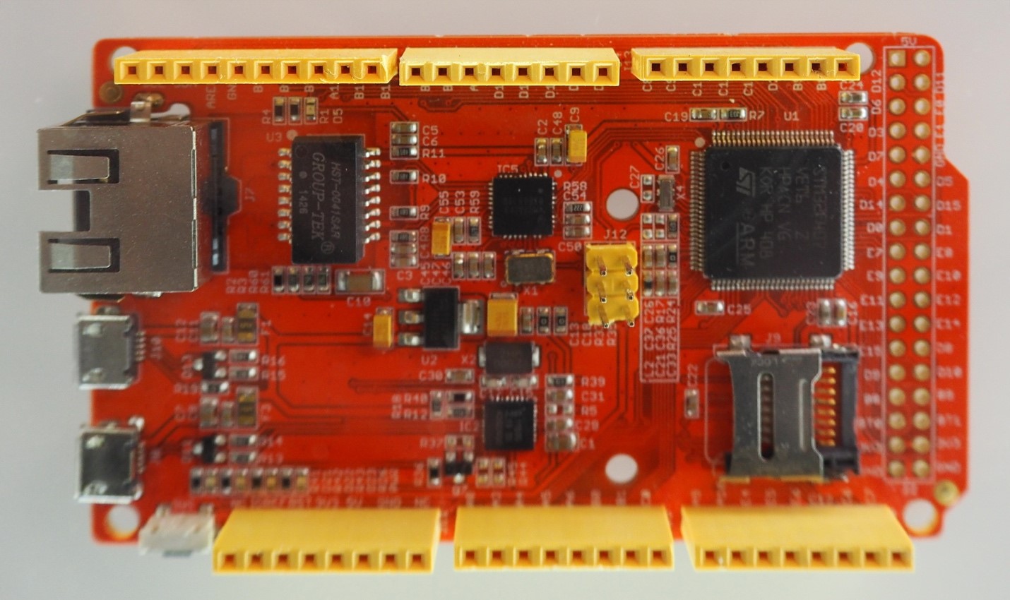
A Beginner’s Guide to Making a STM32 Board

If you’re looking to learn how to make your own electronic devices at home, it’s important to understand that you’re going to need two things: a microprocessor and the microprocessor board to put it on.
In an earlier post, we taught you how to program the PIC16F84A — sometimes known as the “beginner’s microcontroller.” Today, we’ll teach you how to create an STM32 microcontroller board, which is a little more complex. The STM32's pinout requires one of the most flexible PCBs available, making it a perfect fit for many products like printers and robots. No matter what you plan to make first, an STM32 board can help you bring it to life.
But how do you design one? Here are the important steps:
Creating a system design
Every new circuit board starts with a system design. By knowing what parts you need and where to put them, the actual creation of the board will go much faster. A good STM32 design only needs one step: the creation of a block diagram.
Smartdraw is a diagramming tool with a huge, context-sensitive collection of elements you can use to make your circuit design. Here, you can create one block for each of its core functions and components. The diagram also needs to map the connection between each block as well as the voltage level for each connection.
STM32 boards need certain requirements, too, like:
- A 4.7uF and a 100nF capacitor next to the two VDD pins;
- A 1uF and 10nF decoupling capacitors next to the VDDA pin; and
- A maximum voltage of 24mA
Use a JTAG or Serial Wire Debug for your protocol, so it doesn’t mess with the layout.
Choosing a design tool
Now that you have a working STM32 design on paper, it’s time to put that into software. For this, you need a schematic circuit design tool. But with so many of them available on the market, which one should you choose?
For example, Upverter is an open-source program, making it free. And while its features are limited, it does have a very supportive community that can help you design your board. Meanwhile, Altium 365 is a premium design software with neat integrations like SOLIDWORKS and Inventor that help cut design time. SOLIDWORKS, for instance, is an AI routing tool that automatically connects electrical design elements like pins and pads. Think about what you want in a design tool and choose software that best adheres to your needs.
Making the board
Once you’ve completed the STM32 design, you can now assemble your board. You’ll be needing four things: a laser printer, photo paper, a copper board, and 2-3 teaspoons of ferric chloride powder.
Step 1: Grab your photo paper and print your design onto its glossy side. Next, take your copper board and cut it according to the size of the board you just printed. Don’t forget to rub one side of the copper board with steel wool after! This removes the top oxide and photo-resistant layer, which will make the paper stick better.
Step 2: Iron the paper onto the board (the glossy and rubbed side together) and dump it in lukewarm water for 10 minutes. This should “print” the design onto the copper.
Step 3: This is the dangerous part — etching the plate. Experts suggest that you should gently drop the copper plate into a water solution with dissolved ferric chloride powder (it’s very toxic). Ferric chloride removes the outer copper, leaving only the conductive one. Use pliers to take it out of the solution.
Remember: Don’t throw the solution into your sink, please. Dispose of it properly by first diluting the solution with a ton of washing soda. Dave’s Homestead teaches you how to convert baking soda to washing soda in less than an hour.
The washing soda will turn it dry and harmless, allowing you to put it in a garbage bag to dispose.
Once you've taken care of that, then your STM32 board is complete! Take a PCB driller to solder all your components, including the microprocessor, to the board. If you want that commercialized sprayed look, you can also buy solder-resistant paint and apply it.


