
I just got my hands on a STM32F407VET black development board from China and was excited about the possible projects I can build with it. To my demise, there’s not much information about programming the board so I had to find that out by myself. This post is for those who also purchased this board and are having a hard time how to start.
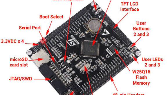
The board comes one of the more popular STM32F407VET Embedded IC and comes with a variety of features:
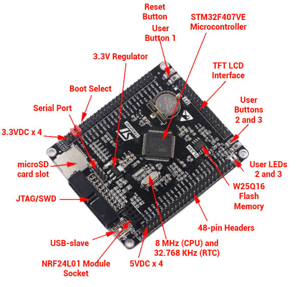
There’s a microSD slot, external flash chip, 3 user buttons, 2 user LEDs, NR24L01 socket, and easily accessible serial pins. I believe these are enough to have a good grasp of using this microcontroller.
The STM32F407VE microcontroller itself packs a punch. It has DSP and Ethernet support not to mention I2S capabilities, a 168-MHz max CPU frequency, 82 (!) GPIOs and USB (with OTG). More information about this microcontroller is in its datasheet.
Not surprisingly, much of the steps in programming this STM32F407VET board is the same as that of the STM32 Blue Pill. We will be using the STM32CubeIDE for writing code and the ST-Link Utility for uploading the program to the board.
Setting Up the Dev Environment
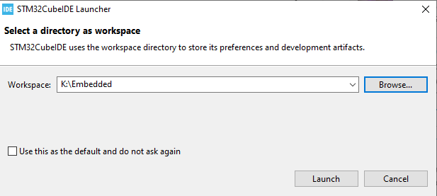
Install and open STM32CubeIDE. If it’s your first time opening it, you’ll need to specify the workspace directory. Tick on the checkbox below to make that workspace default and prevent this window from appearing again.
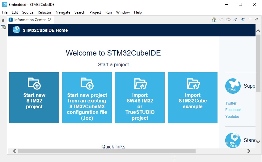
Next, select your project type. We’ll want to start a new project for now so click on Start new STM32 Project.
The next step is to select our target device. On the left panel, type in STM32F407VE in the Part Number field.
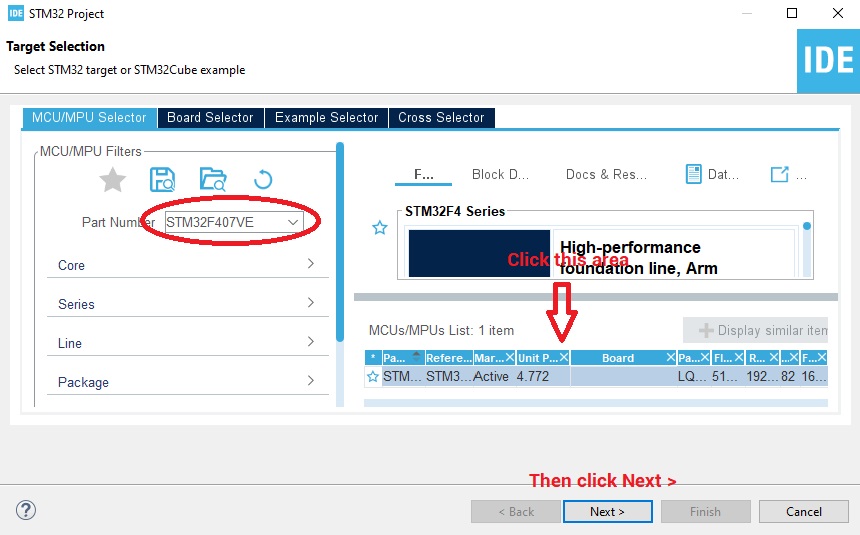
A table will appear on the right panel (see above image). Click on that and then click the Next > button.
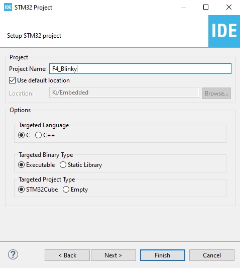
Next, give your project a name. For our example, we’ll name it F4_Blinky.
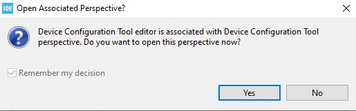
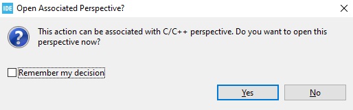
A pop-up window will appear. Click yes to add Associated Perspective to the workspace.
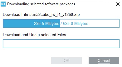
At this point, STM32CubeIDE will start downloading the software packages for the STM32F407VE microcontroller.
Once downloads are finished, you will now be in the Device Configuration Tool. This is a handy tool for configuring the functions of each of the microcontroller’s pins. The tool also allows you to configure the clock for the device, among other features. For more information about this tool, read this specification sheet.
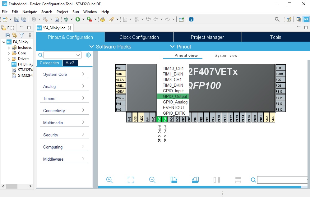
We want to write a code that flashes the two user LEDs.

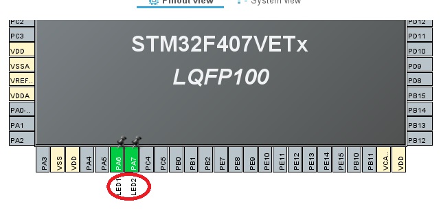
The pinout diagram above shows that the user LEDs LED1 and LED2 (D2 and D3 in the board) connect to GPIOs PA6 and PA7. Hence in the Device Configuration Tool, we click on both pins and change their function to GPIO_OUTPUT.
Next, we click on System Core, then GPIO to reveal the GPIO Mode and Configuration panel. Here we can give a label to pins PA6 and PA7.
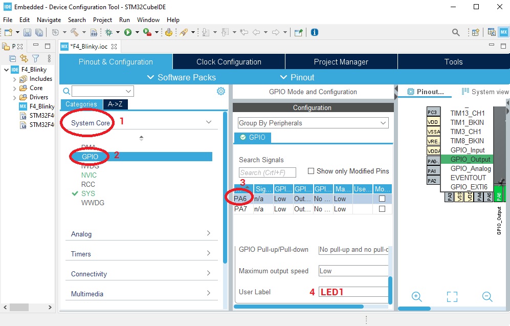
Here I gave the pins the appropriate labels:
Clicking File > Save or pressing CTRL+S will trigger another popup window:
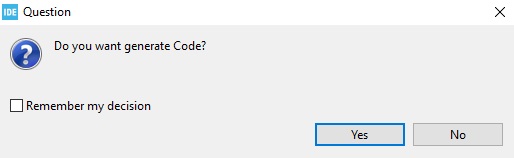
Click Yes and a code with all the configurations will be created automatically!
After that, another window will popup. Clicking Yes to this will add an outline view of your project in the left panel:
Our IDE is now open and we're ready to code!
Writing Code for the STM32F407VE
At this point, we will edit main.c to be able to flash both LED1 and LED2.
Inside the main() function, look for an empty while(1) loop. Whatever is inside this loop is run indefinitely by the microcontroller. Thus, we insert a few lines of code for setting or clearing the user LEDs pin. Here’s how it looks:
while (1)
{
/* USER CODE END WHILE */
  HAL_GPIO_WritePin(GPIOA, LED1_Pin, GPIO_PIN_RESET);
  HAL_GPIO_WritePin(GPIOA, LED2_Pin, GPIO_PIN_SET);
  delay(500000);
  HAL_GPIO_WritePin(GPIOA, LED1_Pin, GPIO_PIN_SET);
  HAL_GPIO_WritePin(GPIOA, LED2_Pin, GPIO_PIN_RESET);
  delay(500000);
/* USER CODE BEGIN 3 */
}
HAL_GPIO_WritePin() is a built-in function for making a pin HIGH or LOW. It accepts three parameters, the first being the pin's PORT, the second is the pin's name and the third parameter is the pin's state. To make a pin LOW, the state is GPIO_PIN_RESET. Otherwise, the state is GPIO_PIN_SET.
Just like in Arduino or PIC, we'll need to configure the LED pins to be output pins. Fortunately, this is already done through the Device Configuration Tool. You'll see the configurations inside the MX_GPIO_Init() function.
Notice that we are using a delay() function. This is in fact not a built-in function and thus must be also added to the main.c file. Find the MX_GPIO_Init() function and after the closing bracket of that function, insert the following:
/* USER CODE BEGIN 4 */

void delay (int a)
{
  volatile int i,j;
  for (i=0 ; i < a ; i++)
  {
    j++;
  }
  return;
}

/* USER CODE END 4 */
This is a function that keeps the microcontroller busy. It uses a for-loop that counts up to the passed parameter (in our code, that value is 500000).
We also need to add a prototype of this function right with the other prototypes. The following lines should be right before the main function:
void SystemClock_Config(void);
static void MX_GPIO_Init(void);
void delay (int a);
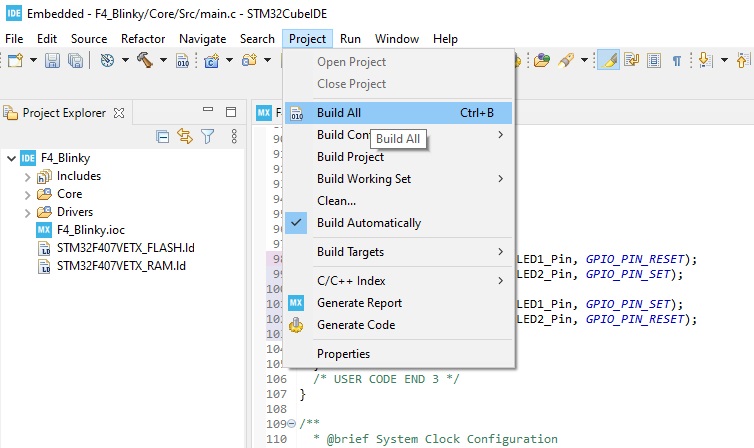
Our code is ready for compilation! Click Project > Build All.
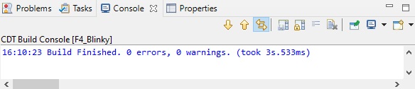
If there are no errors, this should be the output on the console at the bottom:
Uploading Code
A binary file is now inside the folder <Project-Name>/Debug/. Next, it’s time to load this binary file to the microcontroller.
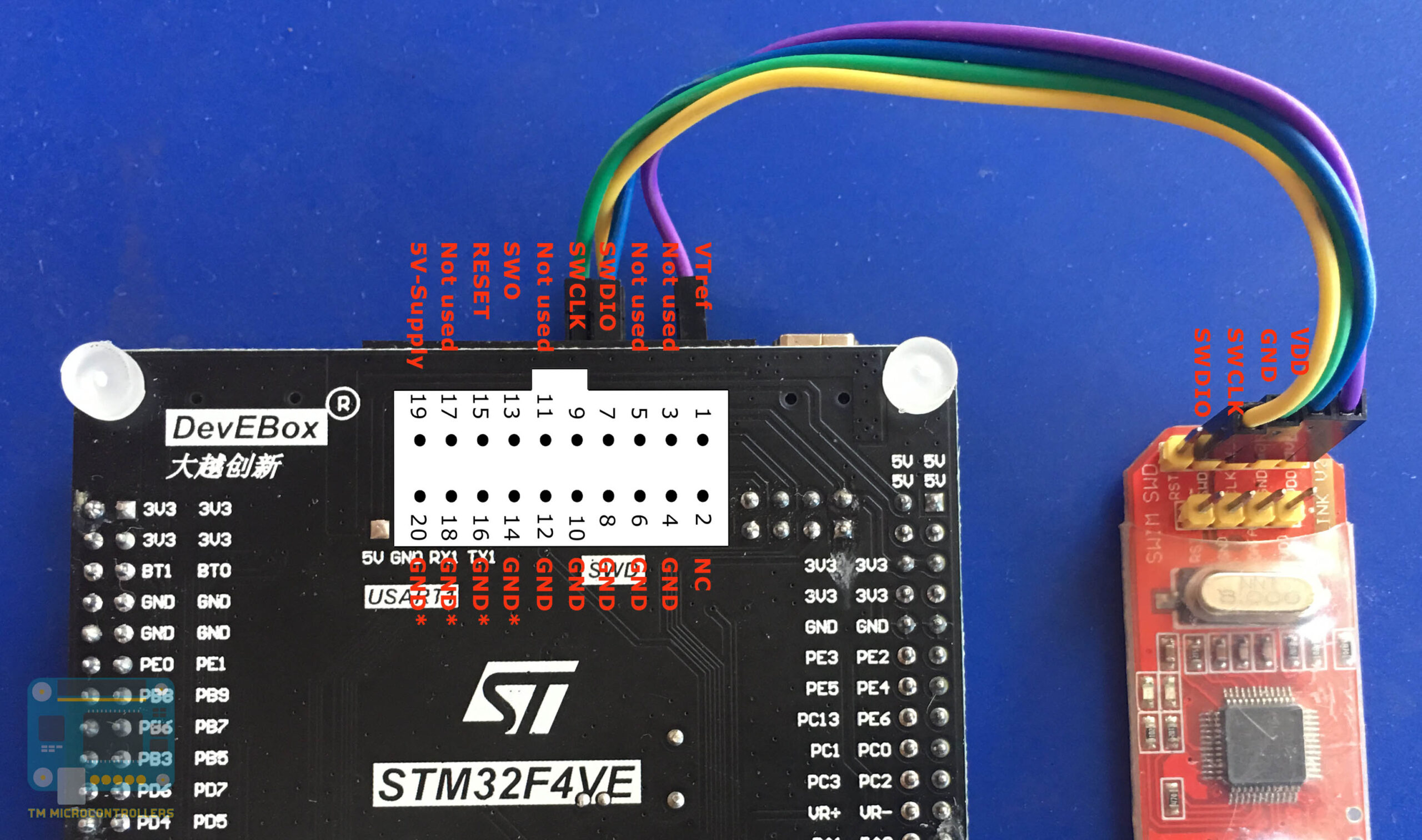
I am using an ST-Link V2 USB dongle with its SWD pins wired to the SWD pins of the STM32F407VE board.
Also, before programming, make sure the BT0 pin is connected to ground and BT1 is wired to 3.3V. Here I am using jumpers to do just that.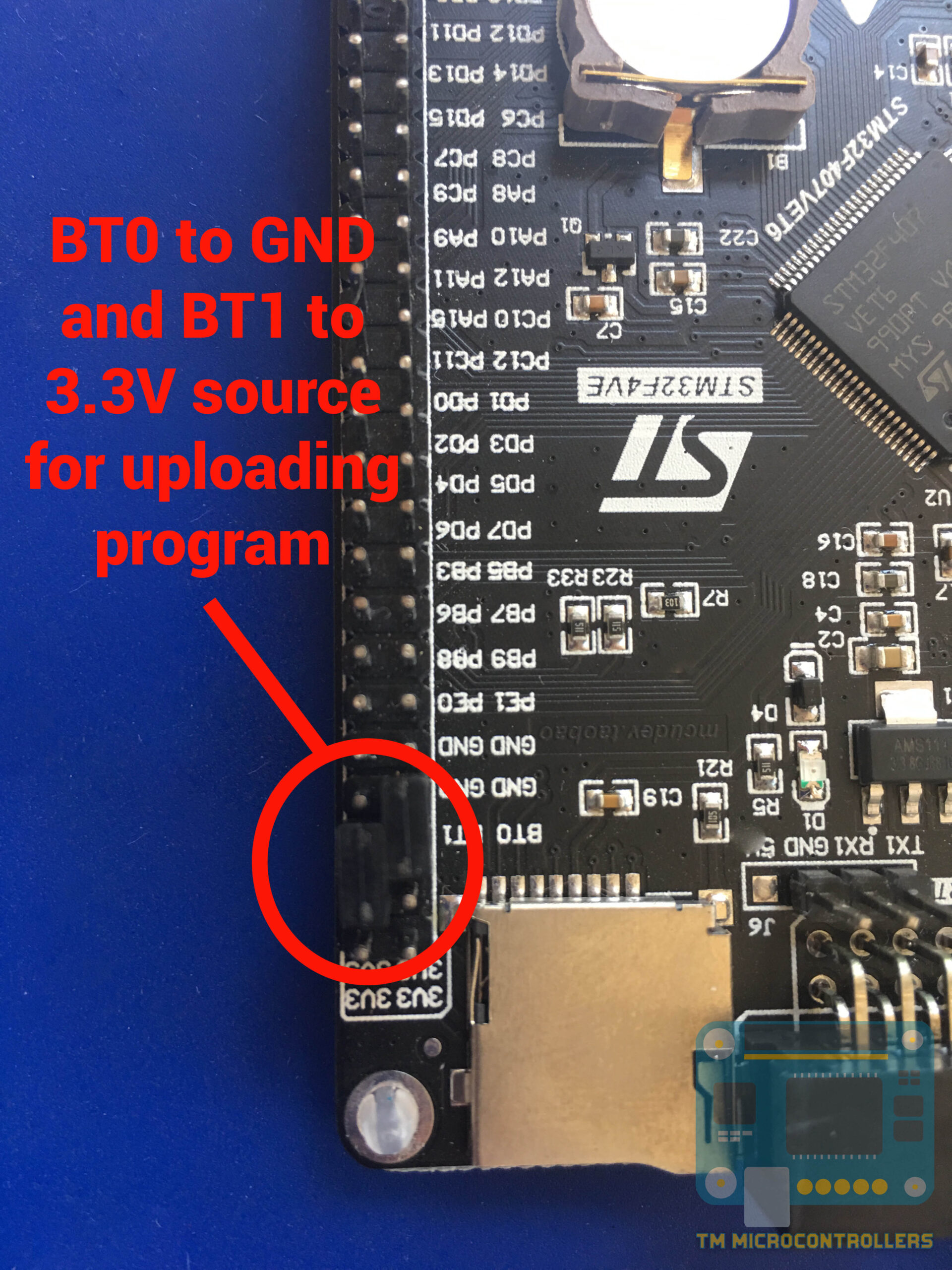
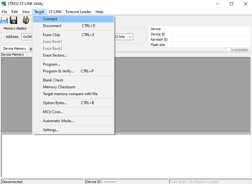
In ST-Link Utility, click Target > Connect.
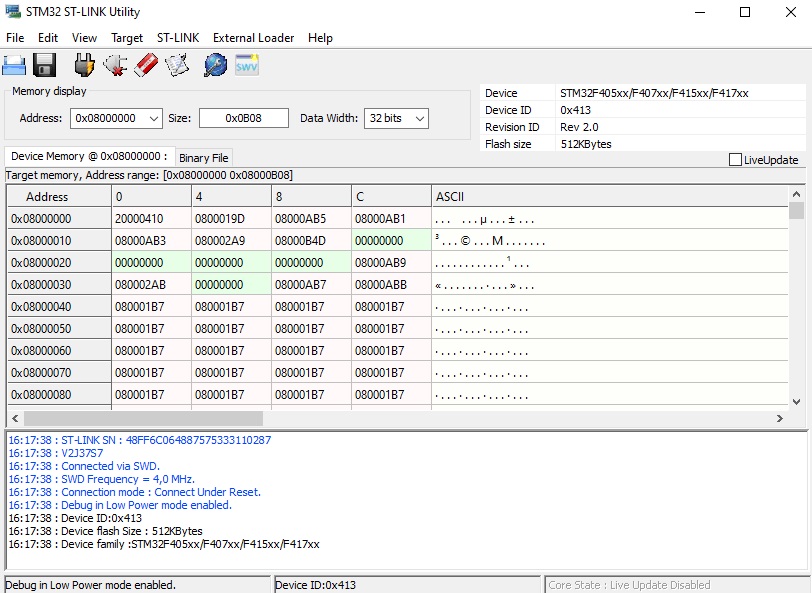
If the data in the memory of the microcontroller is now visible, then the connection is successful:
Next, click File > Open to load the binary file. After that, click Target > Program.
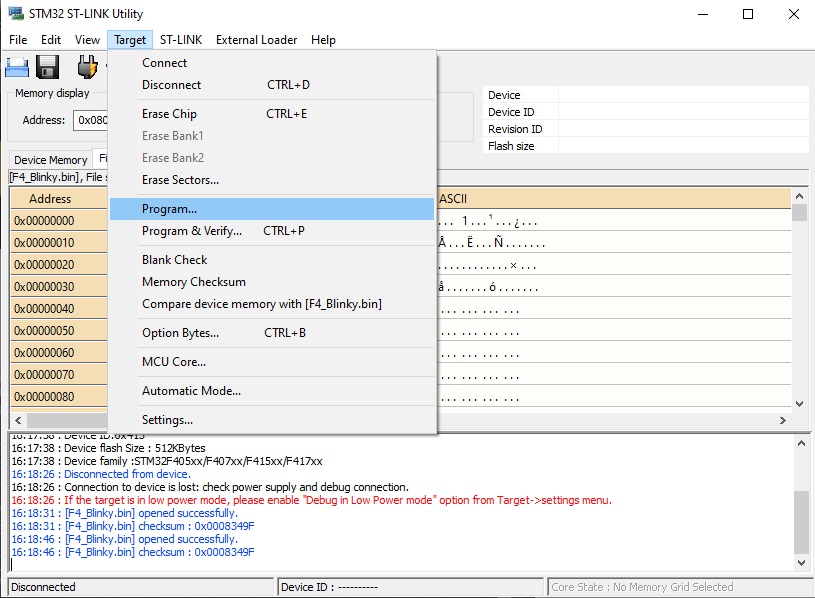
Finally, click Start to initiate the binary transfer:
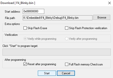
If nothing went wrong, the STM32F407VE board now has a new program!
The LEDs LED1 (D2) and LED2 (D3) should now be flashing alternately.
Have any questions about this tutorial? Feel free to drop a comment below.


Appreciate your effort in posting the entire process. I am sure it will help newbies. There is a function HAL_Delay (mSec) which you can use., Instead of the function you have written. Also one needs to keep in mind, code optimization if selected will remove your delay code as the compiler finds that your code is not doing anything. Once you select release option in project settings code optimization is generally enabled.
Thanks for the info Partha!
Very instructive! Thank you very much.
Hey I recently ordered this board, is it possible to program this board using the onboard usb, instead of using stlink.
Hi,
Yes, it's possible by uploading a code that makes it jump to bootloader. I will post a tutorial about that soon