
This Arduino motion-activated alarm features a tilt sensor for detecting movements and a piezo speaker for producing the siren sound.
Introduction
Basically, the tilt sensor produces a high voltage when it is tilted and a low voltage when it is placed flat on a surface. The siren is produced by increasing a tone frequency from 440 Hertz to 1000 Hertz and then decreasing back to 440 Hertz again with a 5-millisecond delay between increments.
Here’s how the alarm sounds:
Materials
I’m using an Arduino Nano again because I wanted to use my ever-reliable breadboard. The tilt sensor from DFRobot is a digital version of the old mercury switch. This means it’s safer to use. The breakout board, however, doesn’t allow for sensitivity adjustments so I had to deal with its default sensitivity (which is VERY SENSITIVE).
Wiring Diagram
The connections are fairly simple as shown:
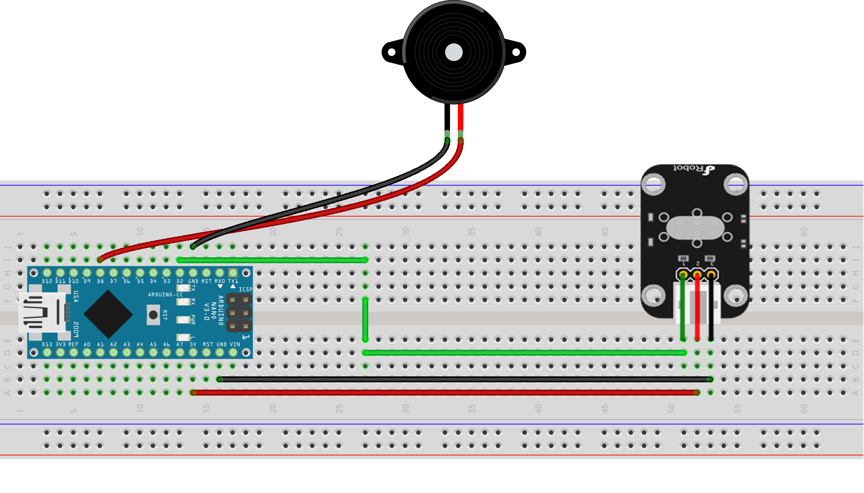
The only requirement is that the piezo speaker must be connected to a PWM pin to produce the tone. Here, I attached it to digital pin 8. The tilt sensor can be connected to any digital pin. Here, I attached it to pin 2.
Arduino Sketch
/*
Motion Activated Alarm/Siren
By Roland

Full tutorial on https://www.teachmemicro.com/arduino-motion-activated-alarm
*/

#define LED 13
#define speakerPin 8
#define tiltSwitch 2

int state = 0;

void setup()
{
    pinMode(LED, OUTPUT);
    pinMode(speakerPin, OUTPUT);
    pinMode(tiltSwitch, INPUT);
}
void loop()
{
    state = digitalRead(tiltSwitch);
    digitalWrite(LED, state);
    if (state == 1)
    {
      for(int hz = 440; hz < 1000; hz++){
        tone(speakerPin, hz, 50);
        delay(5);
      }
      noTone(speakerPin);

      for(int hz = 1000; hz > 440; hz--){
        tone(speakerPin, hz, 50);
        delay(5);
      }
       noTone(speakerPin);
    }
    else{
      noTone(speakerPin);
    }
}
The sketch starts with three defines:
#define LED 13
#define speakerPin 8
#define tiltSwitch 2
This is basically assigning names to pins 13, 8 and 2 to make the program more readable. Obviously, both LED and speakerPin are outputs while the tiltSwitch is input, hence:
pinMode(LED, OUTPUT);
pinMode(speakerPin, OUTPUT);
pinMode(tiltSwitch, INPUT);
This is the only content inside the setup() function.
In the loop() function, the tilt sensor value is checked using
state = digitalRead(tiltSwitch);
If state is high, there is motion. The state variable is used to write a value to the LED pin: if the state variable is high, the LED is also high and vice versa.
The siren routine starts when motion is detected. The siren sound is produced by incrementing a 440 Hz tone to 1000 Hz then decrementing back to 440 Hz with 5 millisecond delay between increments/decrements. The
noTone(speakerPin);
between increment and decrement gives a short pause and makes the sound more authentic.


